
Page 438 - Engineering Digital Design
P. 438
408 CHAPTER 9 / PROPAGATION DELAY AND TIMING DEFECTS
f- N Output
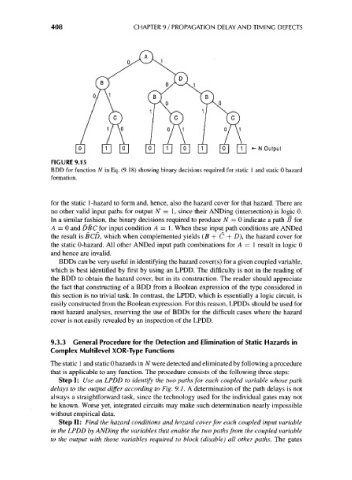
FIGURE 9.15
BDD for function N in Eq. (9.18) showing binary decisions required for static 1 and static 0 hazard
formation.
for the static 1-hazard to form and, hence, also the hazard cover for that hazard. There are
no other valid input paths for output N = I, since their ANDing (intersection) is logic 0.
In a similar fashion, the binary decisions required to produce N = 0 indicate a path B for
A = 0 and DEC for input condition A = 1. When these input path conditions are ANDed
the result is BCD, which when complemented yields (B + C + D), the hazard cover for
the static 0-hazard. All other ANDed input path combinations for A — I result in logic 0
and hence are invalid.
BDDs can be very useful in identifying the hazard cover(s) for a given coupled variable,
which is best identified by first by using an LPDD. The difficulty is not in the reading of
the BDD to obtain the hazard cover, but in its construction. The reader should appreciate
the fact that constructing of a BDD from a Boolean expression of the type considered in
this section is no trivial task. In contrast, the LPDD, which is essentially a logic circuit, is
easily constructed from the Boolean expression. For this reason, LPDDs should be used for
most hazard analyses, reserving the use of BDDs for the difficult cases where the hazard
cover is not easily revealed by an inspection of the LPDD.
9.3.3 General Procedure for the Detection and Elimination of Static Hazards in
Complex Multilevel XOR-Type Functions
The static 1 and static 0 hazards in TV were detected and eliminated by following a procedure
that is applicable to any function. The procedure consists of the following three steps:
Step I: Use an LPDD to identify the two paths for each coupled variable whose path
delays to the output differ according to Fig. 9.1. A determination of the path delays is not
always a straightforward task, since the technology used for the individual gates may not
be known. Worse yet, integrated circuits may make such determination nearly impossible
without empirical data.
Step II: Find the hazard conditions and hazard cover for each coupled input variable
in the LPDD by ANDing the variables that enable the two paths from the coupled variable
to the output with those variables required to block (disable) all other paths. The gates