
Page 442 - Engineering Digital Design
P. 442
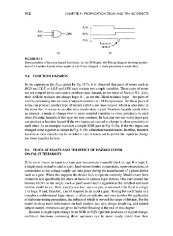
412                     CHAPTER 9 / PROPAGATION DELAY AND TIMING DEFECTS


                                                      B(H) J

                                                                Function
                                                                Hazard
                                       (a)                           (b)
                    FIGURE 9.19
                    Demonstration of function hazard formation, (a) An XOR gate, (b) Timing diagram showing produc-
                    tion of a function hazard when inputs A and B are changed in close proximity to each other.


                    9.4 FUNCTION HAZARDS

                    In the expression for Z SQP given by Eq. (9.7), it is observed that pairs of terms such as
                    BCD and CDE or ADE and ABE each contain two couple variables. These pairs of terms
                    are not coupled terms and cannot produce static hazards in the sense of Section 9.2. Also,
                    their ANDed residues are always logic 0 — as are the ORed residues logic 1 for pairs of
                    s-terms containing two (or more) coupled variables in a POS expression. But these pairs of
                    terms can produce another type of hazard called a function hazard, which is also static in
                    the sense that it occurs in an otherwise steady-state signal. Function hazards result when
                    an attempt is made to change two or more coupled variables in close proximity to each
                    other. Potential hazards of this type are very common. In fact, any two (or more) input gate
                    can produce a function hazard if the two inputs are caused to change in close proximity to
                    each other. As an example, consider a simple XOR gate in Fig. 9.19a. If the two inputs are
                    changed close together as shown in Fig. 9.19b, a function hazard results. In effect, function
                    hazards in most circuits can be avoided if care is taken not to permit the inputs to change
                    too close together in time.


                    9.5 STUCK-AT FAULTS AND THE EFFECT OF HAZARD COVER
                    ON FAULT TESTABILITY

                    If, by some means, an input to a logic gate becomes permanently stuck at logic 0 or logic 1,
                    a single stuck-at fault is said to exist. Inadvertent shorted connections, open connections, or
                    connections to the voltage supply can take place during the manufacture of a given device
                    such as a gate. When this happens the device fails to operate correctly. Models have been
                    created to test specifically for stuck-at faults in various logic devices. One such model has
                    become known as the single stuck-at fault model and is regarded as the simplest and most
                    reliable model to use. Here, exactly one line, say to a gate, is assumed to be fixed at a logic
                    1 or logic 0 and, therefore, cannot respond to an input signal. Testing for such faults in a
                    complex combinational logic circuit is often complicated and may involve the application
                    of elaborate testing procedures, the subject of which is beyond the scope of this text. For the
                    reader wishing more information on fault models, test sets, design testability, and related
                    subject matter, references are given in Further Reading at the end of this chapter.
                      Because a single input change to an XOR or EQV operator produces an output change,
                    multilevel functions containing these operators can be more easily tested than their