
Page 528 - Engineering Digital Design
P. 528
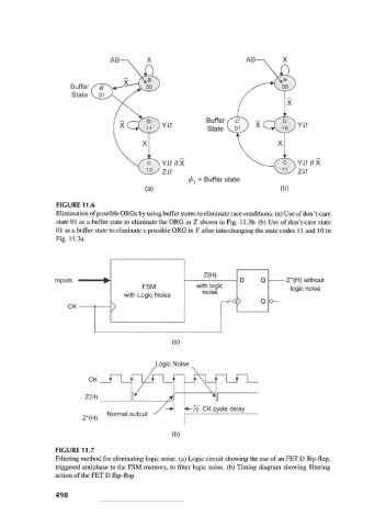
Buffer
                         State


                                                            Buffer
                                                            State V01


                                                YitifX
                                                       ^ 1 = Buffer state
                                            (a)                                (b)
                     FIGURE 11.6
                     Elimination of possible ORGs by using buffer states to eliminate race conditions, (a) Use of don't-care
                     state 01 as a buffer state to eliminate the ORG in Z shown in Fig. 11.3b. (b) Use of don't-care state
                     01 as a buffer state to eliminate a possible ORG in Y after interchanging the state codes 11 and 10 in
                     Fig. 11.3a.


                                                            Z(H)
                      Inputs                                          D    Q      Z*(H) without
                                   *         FSM          with logic               logic noise
                                                            noise
                                        with Logic Noise
                                                                  7
                                                                 r ^- >    Q
                         CK
                                    ^

                                                    (a)

                                                Logic Noise


                                                    (b)
                     FIGURE 11.7
                     Filtering method for eliminating logic noise, (a) Logic circuit showing the use of an FET D flip-flop,
                     triggered antiphase to the FSM memory, to filter logic noise, (b) Timing diagram showing filtering
                     action of the FET D flip-flop.

                     498