
Page 531 - Engineering Digital Design
P. 531
11.3 DETECTION AND ELIMINATION OF STATIC HAZARDS 501
Z pos = (B+Y)(A+Y)
11 11 (NA)
(a) (b) (c)
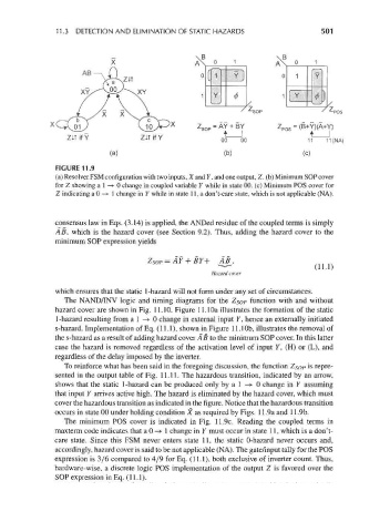
FIGURE 11.9
(a) Resolver FSM configuration with two inputs, X and Y, and one output, Z. (b) Minimum SOP cover
for Z showing a 1 —> 0 change in coupled variable Y while in state 00. (c) Minimum POS cover for
Z indicating a 0 —> 1 change in Y while in state 11, a don't-care state, which is not applicable (NA).
consensus law in Eqs. (3.14) is applied, the ANDed residue of the coupled terms is simply
AB, which is the hazard cover (see Section 9.2). Thus, adding the hazard cover to the
minimum SOP expression yields
Z SOP=AY + BY+ A&,
v
( A * • • * • )
Hazard cover
which ensures that the static 1-hazard will not form under any set of circumstances.
The NAND/INV logic and timing diagrams for the Z SOp function with and without
hazard cover are shown in Fig. 11.10. Figure 11.1 Oa illustrates the formation of the static
1-hazard resulting from a 1 —> 0 change in external input Y, hence an externally initiated
s-hazard. Implementation of Eq. (11.1), shown in Figure 11.1 Ob, illustrates the removal of
the s-hazard as a result of adding hazard cover A B to the minimum SOP cover. In this latter
case the hazard is removed regardless of the activation level of input 7, (H) or (L), and
regardless of the delay imposed by the inverter.
To reinforce what has been said in the foregoing discussion, the function ZSOP is repre-
sented in the output table of Fig. 11.11. The hazardous transition, indicated by an arrow,
shows that the static 1-hazard can be produced only by a 1 —>• 0 change in Y assuming
that input Y arrives active high. The hazard is eliminated by the hazard cover, which must
cover the hazardous transition as indicated in the figure. Notice that the hazardous transition
occurs in state 00 under holding condition X as required by Figs. 11.9a and 11.9b.
The minimum POS cover is indicated in Fig. 11.9c. Reading the coupled terms in
maxterm code indicates that a 0 —» 1 change in Y must occur in state 11, which is a don't-
care state. Since this FSM never enters state 11, the static 0-hazard never occurs and,
accordingly, hazard cover is said to be not applicable (NA). The gate/input tally for the POS
expression is 3/6 compared to 4/9 for Eq. (11.1), both exclusive of inverter count. Thus,
hardware-wise, a discrete logic POS implementation of the output Z is favored over the
SOP expression in Eq. (11.1).