
Page 534 - Engineering Digital Design
P. 534
504 CHAPTER 11 / SYNCHRONOUS FSM DESIGN CONSIDERATIONS
S(L) 1
R(L) 1
— * 'ft— T -i >-*• l«— T
Q(H) _j T
-+! '<«— T — »> «— T
R(L)
o^r,
SOP Q(H) leads Q(L) Q(L) leads Q(H)
Basic cell N ^ '
Conditions for POS hazard formation
(a)
S(H) 1
R(H) r l
— ir* •«— T
Q(H) , i_j
T -r
L
S(H) i * >^*-Q( )
POS Q(L) leads Q(H) Q(H) leads Q(L)
Basic cell v \/ x
Conditions for SOP hazard formation
(b)
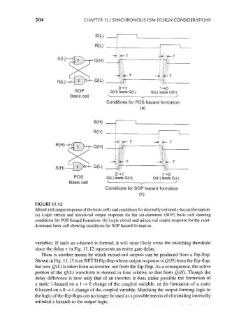
FIGURE 11.12
Mixed-rail output response of the basic cells and conditions for internally initiated s-hazard formation,
(a) Logic circuit and mixed-rail output response for the set-dominant (SOP) basic cell showing
conditions for POS hazard formation, (b) Logic circuit and mixed-rail output response for the reset-
dominant basic cell showing conditions for SOP hazard formation.
variable). If such an s-hazard is formed, it will most likely cross the switching threshold
since the delay T in Fig. 11.12 represents an entire gate delay.
There is another means by which mixed-rail outputs can be produced from a flip-flop.
Shown in Fig. 11.13 is an RET D flip-flop whose output response is Q(H) from the flip-flop,
but now Q(L) is taken from an inverter, not from the flip-flop. As a consequence, the active
portion of the Q(L) waveform is skewed in time relative to that from Q(H). Though the
delay difference is now only that of an inverter, it does make possible the formation of
a static 1-hazard on a 1 ->• 0 change of the coupled variable, or the formation of a static
0-hazard on a 0 ->• 1 change of the coupled variable. Matching the output-forming logic to
the logic of the flip-flops can no longer be used as a possible means of eliminating internally
initiated s-hazards in the output logic.