
Page 536 - Engineering Digital Design
P. 536
506 CHAPTER 11 / SYNCHRONOUS FSM DESIGN CONSIDERATIONS
Choice in use of ^
YiTifS
Late deactiyation
of Y if ST
(a) (b)
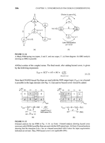
FIGURE 11.14
A Mealy FSM having two inputs, 5 and T, and one output, Y. (a) State diagram, (b) ORG analysis
showing no ORG is possible.
ANDed residue of the coupled terms. The final result, after adding hazard cover, is given
by the following expression:
YSOP = ACT + AS + BC+ csr.
v
(AA--^/
Hazard cover
Note that if NAND-based flip-flops are used with the SOP output logic (Y Sop), no s-hazard
is possible in the logic domain (see Fig. 11.12a) and no hazard cover should be added.
\BC
A\ 00 01 11 10 A\ 00 01 11 10
0 1° T ) 1 0
1
1 S $ <•)
^
'SOP ' ,v~
Y SOP = ACT + AS + BC + CST Y pos = (A + B + T)(A + S>C
T ST T Hazard cover if T st T
071 _ 171 NOR-basedFFs 00? 10? (NA)
001 -§^> 101
(a) (b)
FIGURE 11.15
S-hazard analysis for the FSM in Fig. 11.14. (a) Static 1-hazard analysis showing hazard cover
necessary only if NOR-based flip-flops are used with the SOP output logic, (b) Static 0-hazard analysis
showing that the transition b-to-c has no s-hazard associated with it since the input requirements
indicated are not met. Thus, POS hazard cover is not applicable (NA).