
Page 541 - Engineering Digital Design
P. 541
11.4 ASYNCHRONOUS INPUTS: RULES AND CAVEATS 511
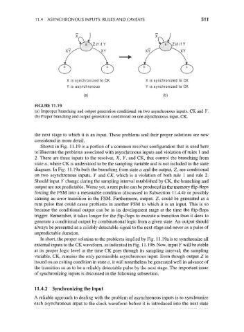
X is synchronized to CK X is synchronized to CK
Y is asynchronous Y is synchronized to CK
(a) (b)
FIGURE 11.19
(a) Improper branching and output generation conditional on two asynchronous inputs, CK and Y.
(b) Proper branching and output generation conditional on one asynchronous input, CK.
the next stage to which it is an input. These problems and their proper solutions are now
considered in more detail.
Shown in Fig. 11.19 is a portion of a common resolver configuration that is used here
to illustrate the problems associated with asynchronous inputs and violation of rules 1 and
2. There are three inputs to the resolver, X, Y, and CK, that control the branching from
state a, where CK is understood to be the sampling variable and is not included in the state
diagram. In Fig. 11.19a both the branching from state a and the output, Z, are conditional
on two asynchronous inputs, Y and CK, which is a violation of both rule 1 and rule 2.
Should input Y change during the sampling interval established by CK, the branching and
output are not predictable. Worse yet, a runt pulse can be produced in the memory flip-flops
forcing the FSM into a metastable condition (discussed in Subsection 11.4.4) or possibly
causing an error transition in the FSM. Furthermore, output, Z, could be generated as a
runt pulse that could cause problems in another FSM to which it is an input. This is so
because the conditional output can be in its development stage at the time the flip-flops
trigger. Remember, it takes longer for the flip-flops to execute a transition than it does to
generate a conditional output by combinational logic from a given state. An output should
always be presented as a reliably detectable signal to the next stage and never as a pulse of
unpredictable duration.
In short, the proper solution to the problems implied by Fig. 11.19a is to synchronize all
external inputs to the CK waveform, as indicated in Fig. 11.19b. Now, input Y will be stable
at its proper logic level at the time CK goes through its sampling interval; the sampling
variable, CK, remains the only permissible asynchronous input. Even though output Z is
issued on an exiting condition in state a, it will nonetheless be generated well in advance of
the transition so as to be a reliably detectable pulse by the next stage. The important issue
of synchronizing inputs is discussed in the following subsection.
11.4.2 Synchronizing the Input
A reliable approach to dealing with the problem of asynchronous inputs is to synchronize
each asynchronous input to the clock waveform before it is introduced into the next state