
Page 543 - Engineering Digital Design
P. 543
11.4 ASYNCHRONOUS INPUTS: RULES AND CAVEATS 513
Stretcher Synchronizer
/
X(L)
Narrow and
asynchronous
Input |—c R Q D— , _ CGKA 1*. Outputs
Q(H)
X'(L) = R(L)
X'(H)
(b)
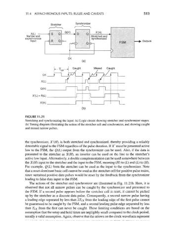
FIGURE 11.21
Stretching and synchronizing the input, (a) Logic circuit showing stretcher and synchronizer stages,
(b) Timing diagram illustrating the action of the stretcher cell and synchronizer, and showing caught
and missed narrow pulses.
the synchronizer, X'(H), is both stretched and synchronized, thereby providing a reliably
detectable signal to the FSM regardless of the pulse duration. If X' must be presented active
low to the FSM, the Q(L) output from the synchronizer can be used. Also, if the data is
presented to the stretcher as X(tf), an inverter can be used on the line to the stretcher's
active low input. Alternatively, a double complementation can be used somewhere between
the X(H) input to the stretcher and the input to the FSM, meaning (//) to (L) and (L) to (H).
For example, Q(L) from the stretcher can be used as the input to the synchronizer. Note
that a reset-dominant basic cell cannot be used as the stretcher cell for positive pulse trains,
since sustained positive data pulses would be reset by the feedback from the synchronizer
leading to false data input to the FSM.
The actions of the stretcher and synchronizer are illustrated in Fig. 11.21b. Here, it is
observed that not all narrow pulses can be caught by the synchronizer and presented to
the FSM. If a second pulse appears before the stretcher cell is reset, it cannot be picked
up by the stretcher as a discrete data pulse. Consequently, a second narrow pulse having
a leading edge separated by less than 2T CK from the leading edge of the first pulse cannot
be guaranteed to be caught by the FSM, and a second leading pulse edge separated by less
than TCK from the first can never be caught. These limiting conditions are based on the
assumption that the setup and hold times are negligibly small compared to the clock period,
usually a valid assumption. Again, observe that the arrows on the clock waveform represent