
Page 545 - Engineering Digital Design
P. 545
11.4 ASYNCHRONOUS INPUTS: RULES AND CAVEATS 515
cannot be predicted. But this is probably a moot point, since an oscillatory condition can
potentiallly cause far more serious problems than an unpredictable outcome following exit
from that state.
The foregoing discussion applies to any FSM, including flip-flops. As an example, the
resolver section of a D flip-flop shown in Fig. 10.3la can go metastable and cause both
the flip-flop and the FSM in which it is operating to malfunction. Thus, the synchronizer
in Fig. 11.20a is subject to the metastable condition and can pass that metastable state on
Two stage synchronizer
\
Stage 1 Stage 2 Insert to (a)
Qi(H) X'(H)
X(ll) D Q D Q "> " f i!' Sl
.,1 . ,; ; ' r ;«'
r^-C >;; ; Q o r^C \ Q Q- ,'* ; ! " 1CNT
i/x; Divide-by-2
CNT
CK-f-| CNT M L ^ i—I I 1 PSM -^ Outputs
|-
M
counter
1
/a *
Sampling interval
CK
'CK
X(H) A I
° l(H) ^"7^ dH X(H)
Metastability disappears after_y
metastable exit time At Normal •
transition \
X'(H) : -
Possible runt
V Synchronizer 4 pulse into FF
T
- triggering edge
(No counter)
(b) (c)
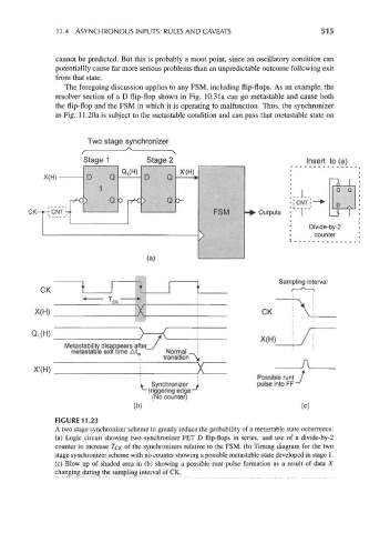
FIGURE 11.23
A two stage synchronizer scheme to greatly reduce the probability of a metastable state occurrence,
(a) Logic circuit showing two synchronizer FET D flip-flops in series, and use of a divide-by-2
counter to increase TCK of the synchronizers relative to the FSM. (b) Timing diagram for the two
stage synchronizer scheme with no counter showing a possible metastable state developed in stage 1.
(c) Blow up of shaded area in (b) showing a possible runt pulse formation as a result of data X
changing during the sampling interval of CK.