Page 546 - Engineering Digital Design
P. 546
516                 CHAPTER 11 /SYNCHRONOUS FSM DESIGN CONSIDERATIONS


                     to the FSM it is supposed to protect. A practical solution is illustrated by the two-stage
                     synchronizer configuration shown in Fig. 11.23a. The idea depicted here is that in the event
                     synchronizer 1 should go metastable, it would emerge from that metastable state long before
                     synchronizer 2 is triggered, as illustrated in Fig. 11.23b. This, in turn, greatly reduces the
                     probability that synchronizer 2 will become metastable and cause malfunction of the FSM.
                     Of course, it is assumed that the metastable exit time, At m, will always be less than T CK, an
                     assumption that may or may not be valid.
                       The blown-up region in Fig. 11.23c illustrates one means by which a metastable state
                     can be introduced into stage 1 of the synchronizer. If asynchronous input X(H) changes
                     during the sampling interval of clock, a runt pulse could form and be introduced into the
                     D flip-flop as neither a set nor a reset condition, and this could initiate the metastable state.
                     Such a runt pulse could cross the switching threshold but lack the "strength" or duration
                     needed to resolve the flip-flop into a set (or reset) condition, and a metastable condition
                     could result.
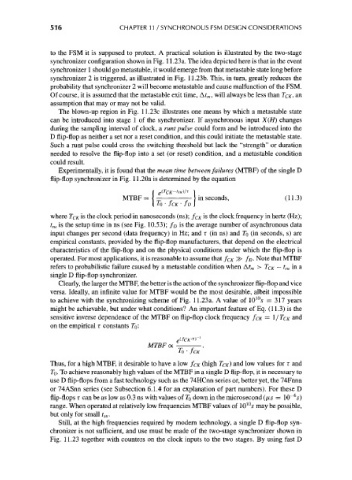
                       Experimentally, it is found that the mean time between failures (MTBF) of the single D
                     flip-flop synchronizer in Fig. 11.20a is determined by the equation

                                         MTBF = {             [ in seconds,             (11.3)
                                                  [ TO • JCK • JD \
                     where TCK is the clock period in nanoseconds (ns); f CK is the clock frequency in hertz (Hz);
                     t su is the setup time in ns (see Fig. 10.53); f D is the average number of asynchronous data
                     input changes per second (data frequency) in Hz; and r (in ns) and TO (in seconds, s) are
                     empirical constants, provided by the flip-flop manufacturers, that depend on the electrical
                     characteristics of the flip-flop and on the physical conditions under which the flip-flop is
                     operated. For most applications, it is reasonable to assume that f CK ^> f D. Note that MTBF
                     refers to probabilistic failure caused by a metastable condition when At m > TCK — t su in a
                     single D flip-flop synchronizer.
                       Clearly, the larger the MTBF, the better is the action of the synchronizer flip-flop and vice
                     versa. Ideally, an infinite value for MTBF would be the most desirable, albeit impossible
                                                                               10
                     to achieve with the synchronizing scheme of Fig. 11.23a. A value of 10 s = 317 years
                     might be achievable, but under what conditions? An important feature of Eq. (11.3) is the
                     sensitive inverse dependence of the MTBF on flip-flop clock frequency /CK = I/ TCK and
                     on the empirical r constants 7b:

                                                MTBFoc
                                                         TO • fcK

                     Thus, for a high MTBF, it desirable to have a low /CK (high TCK) and low values for r and
                     TQ. To achieve reasonably high values of the MTBF in a single D flip-flop, it is necessary to
                     use D flip-flops from a fast technology such as the 74HCnn series or, better yet, the 74Fnnn
                     or 74ASnn series (see Subsection 6.1.4 for an explanation of part numbers). For these D
                                                                                          6
                     flip-flops T can be as low as 0.3 ns with values of T 0 down in the microsecond (/JLS = 10~ s)
                     range. When operated at relatively low frequencies MTBF values of 10'°s may be possible,
                     but only for small t m.
                       Still, at the high frequencies required by modern technology, a single D flip-flop syn-
                     chronizer is not sufficient, and use must be made of the two-stage synchronizer shown in
                     Fig. 11.23 together with counters on the clock inputs to the two stages. By using fast D

