
Page 547 - Engineering Digital Design
P. 547
11.5 CLOCK SKEW 517
flip-flop technology and by creating a large T CK for the synchronizers relative to the FSM,
large values of the MTBF can be achieved even with high frequencies. Note that use of a
delay circuit in place of the counter would be worse than having no delay at all. A divide-
by-2 counter doubles the clock period (see Subsection 12.3.1). Now, the clock period for
the two synchronizers is at least double that of the FSM, greatly improving chances for
2T CK > Af m . The divide-by-2 counter should be the slow 74SL74 with a Q(L) -> D(H)
feedback as indicated in the insert to Fig. 11.23a. If this is not sufficient, there are other
alternatives. One alternative is to replace the divide-by-2 counter in Fig. 11.23a by a divide-
by-4 ripple counter (see Section 12.5 for details). As another alternative, a multiple-stage
synchronizer scheme can be used with or without a counter on the clock inputs to the stages
as in Fig. 11.23. Also, Schmitt triggers can be used on the data lines between stages for
additional discrimination of a metastable signal.
All of the synchronizing schemes just mentioned are used at the expense of system
throughput, the price that must be paid to introduce reliably readable data to the protected
FSM. Also, it must be remembered that because metastability is a statistical phenomenon
and is unpredictable, no synchronizer "fix-it" scheme can be devised that will eliminate
entirely the possible occurrence of the metastable state. All that can be done is to reduce
the probability for metastability occurrence to acceptable levels for a given application. In
Chapter 16 an externally asynchronous/internally clocked (EAIC) system will be discussed
that will deal with the problem in a different and more effective manner. EAIC configurations
are pausable systems capable of yielding an infinite MTBF value with no required external
synchronizing logic of the type shown in Fig. 11.23.
11.5 CLOCK SKEW
In synchronous sequential machines the triggering edge of the clock waveform is assumed
to reach each flip-flop of the memory at approximately the same time. Sometimes, however,
this does not happen because of the presence of asymmetric path delays caused mainly by
resistance and parasitic capacitance effects in the clock leads to the memory devices or by
poor clock buffering methods. When such delays become large enough to cause a shift in
the triggering edge of one flip-flop relative to another, clock skew is said to exist. Clock
skew can become a serious problem in digital systems, particularly in complex systems
operated at very high frequencies.
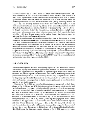
Illustrated in Fig. 11.24 is one type of problem that can occur as a result of clock skew.
Shown in Fig. 11.24a are two RET D flip-flops configured in series with delays A.t\ and
A?2 indicated on the clock inputs to flip-flops 1 and 2, respectively. If the delays are equal,
A?2 = A?i = 0, no clock skew exists and proper flip-flop output response to a change in
data input X(H) results, as indicated in Fig. 11.24b. Observe that X(H) is synchronized to
the falling edge of the CK = CKj waveform. On the other hand, the condition A?2 > A?i
can result in an erroneous output, as indicated in Fig. 11.24c. Such an error will occur
in output Q2(H) if A?2 — &t\ > Tff, where rg is the flip-flop propagation delay. Timing
anomalies of this type can lead to unrecoverable errors in the operation of shift registers
and other devices. The reverse skew, A?i > Afz, on the other hand, will not cause an
output error in these devices, but will delay the issuance of the outputs by the amount of
the skew At\ > A?2- The subject of shift registers will be discussed in detail in Section
12.2. Finally, note that if the configuration indicated in Fig. 11.24 is used as a two-stage