
Page 550 - Engineering Digital Design
P. 550
520 CHAPTER 11 / SYNCHRONOUS FSM DESIGN CONSIDERATIONS
a circuit or programming the routing paths in FPGAs. Try to avoid obvious sources of
asymmetric path delays, particularly those associated with the system clock leads. Often, a
conscious effort in this regard can save much time and expense.
11.6 CLOCK SOURCES AND CLOCK SIGNAL SPECIFICATIONS
Various timing problems relative to the clock waveform have been discussed, but no mention
has been made of the clock signal source and specifications. How, in fact, is a high-frequency,
highly precise clock waveform produced, and how must it be specified so as to perform
predictably as the system clock to a synchronous FSM? The answer is not a simple one,
but it can be dealt with in semiquantitative terms. First, there must be a reference frequency
source, one that has the following desirable characteristics:
High-frequency capability
Frequency stability
Starting reliability
Duty cycle control
Reasonable square-wave output capability
11.6.1 Clock-Generating Circuitry
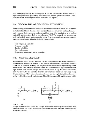
Shown in Fig. 11.26 are two oscillator circuits that possess characteristics suitable for
rather different applications. Figure 11.26a presents an inexpensive self-starting oscillator
circuit that is limited to relatively low frequencies that are somewhat adjustable by the RC
time constant. This particular oscillator circuit has little or no useful application in modern
sophisticated state machine design. The oscillator circuit in Fig. 11.26b is considerably
more expensive, but has all of the desirable characteristics mentioned previously except
duty cycle control. There are oscillator circuits more and less sophisticated than that shown
in Fig. 11.26b. However, all oscillators capable of delivering a stable high frequency within
j—0° ] l( 0
Output, f 0 * Ix —f—°D>— Output, f 0
—1— Q
T
Quartz
(a) crystal
(b)
FIGURE 11.26
Example of clock oscillator circuits, (a) A simple, inexpensive, self-starting oscillator circuit that is
frequency limited, (b) A high-frequency, crystal-controlled oscillator with good starting capability
and frequency stability.