
Page 553 - Engineering Digital Design
P. 553
11.7 INITIALIZATION AND RESET OF THE FSM: SANITY CIRCUITS 523
result. Take, for example, the cruise control of an automobile. Failure of it to initialize or
reset into a startup state could be disastrous. Imagine not being able to initialize or reset
the controller of one's computer. Equally important, no FSM should ever be designed such
that it can initialize or reset into a "hang" state or subroutine that is not part of the intended
sequence. Whether the FSM is the controller for an elevator or traffic light system, or the
controller for a robotics or audio playback system, it should be obvious that initialization
and reset capabilities are vitally important.
11.7.1 Sanity Circuits
What is needed for initialization and reset of the FSM is a signal that can be used to drive
an FSM momentarily into a specific starting or reference state whenever it is necessary to
do so — that is, during power-up to initialize the FSM or during a reset operation. Shown in
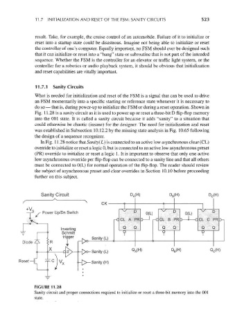
Fig. 11.28 is a sanity circuit as it is used to power up or reset a three-bit D flip-flop memory
into the 001 state. It is called a sanity circuit because it adds "sanity" to a situation that
could otherwise be chaotic (insane) for the designer. The need for initialization and reset
was established in Subsection 10.12.2 by the missing state analysis in Fig. 10.65 following
the design of a sequence recognizer.
In Fig. 11.28 notice that Sanity(L) is connected to an active low asynchronous clear (CL)
override to initialize or reset a logic 0, but is connected to an active low asynchronous preset
(PR) override to initialize or reset a logic 1. It is important to observe that only one active
low asynchronous override per flip-flop can be connected to a sanity line and that all others
must be connected to 0(L) for normal operation of the flip-flop. The reader should review
the subject of asynchronous preset and clear overrides in Section 10.10 before proceeding
further on this subject.
Sanity Circuit D A(H) D B(H) D C(H)
Power Up/Dn Switch
Inverting
Schmitt
tr er
'99 Sanity (L)
—
r^»
H
Sanity (L) Q A( ) Q B(H) Q C(H)
Reset-|[ ^p C J V x , _£>_sanity (H)
I ,, I
FIGURE 11.28
NliUKt 11.28
Sanity circuit and proper connections required to initialize or reset a three-bit memory into the 001