
Page 557 - Engineering Digital Design
P. 557
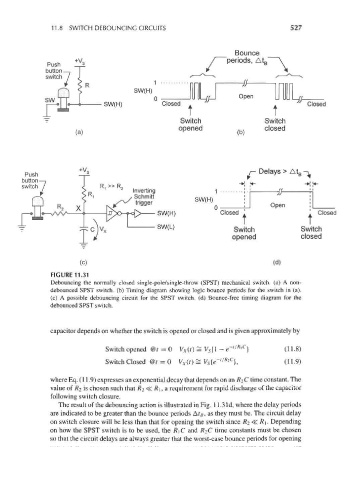
11.8 SWITCH DEBOUNCING CIRCUITS                                      527


                                                                       Bounce
                                                               /periods , At B"
                         +v s
                 Push
                 button —,
                 switch /


                                                  Closed .

                                                       Switch
                                                       opened
                         (a)


           Push             -                                             /-Delays >At B- lf
          button—,                                                      -K  T
          switch                                                           !*-            -*!«-
                                                                 1                if—
                                                           SW(H)
                                                                                 Open
                                                                 0
                                                                  Closed  A                 I Closed
                                                                        t                  t
                                                                      Switch             Switch
                                                                      opened             closed


                           (c)                                                   (d)
                  FIGURE 11.31
                  Debouncing the normally closed single-pole/single-throw (SPST) mechanical switch, (a) A non-
                  debounced SPST switch, (b) Timing diagram showing logic bounce periods for the switch in (a),
                  (c) A possible debouncing circuit for the SPST switch, (d) Bounce-free timing diagram for the
                  debounced SPST switch.


                  capacitor depends on whether the switch is opened or closed and is given approximately by
                                                                       /RlC
                                  Switch opened @t = 0 V x(t) = V s{\ - e~'  }       (11.8)
                                                                   /R2C
                                  Switch Closed @t = 0 V x(t) = V s{e-'  },          (11.9)
                  where Eq. (11.9) expresses an exponential decay that depends on an R^C time constant. The
                  value of ^2 is chosen such that 7? 2 <?C R\, a requirement for rapid discharge of the capacitor
                  following switch closure.
                     The result of the debouncing action is illustrated in Fig. 11.3 Id, where the delay periods
                  are indicated to be greater than the bounce periods Af B , as they must be. The circuit delay
                  on switch closure will be less than that for opening the switch since R^<^R\. Depending
                  on how the SPST switch is to be used, the R\C and R 2C time constants must be chosen
                  so that the circuit delays are always greater that the worst-case bounce periods for opening