
Page 573 - Engineering Digital Design
P. 573
11.11 ARRAY ALGEBRAIC APPROACH TO LOGIC DESIGN 543
The D matrix is formed by combining all states in a given column that are associated with
a holding condition. For example, state set {abc} is associated with the holding condition b
in the /o column. Similarly, state set {de} is associated with holding condition e in the same
column. Notice that all state set entries involving two or more states in the D matrix are an
expression of rule 1, as indicated in Fig. 11.43a. Single literals appear when a present state
identifier is associated exclusively with a holding condition, as in row 1 columns 3 and 4
or in row 5 column 3 of Fig. 11.43a. A zero appears when there is no next state associated
with the present state.
1
By taking the transpose of the S matrix (S ) and Boolean multiplying it with the D matrix
there results the function matrix FNS given by
0 ae a a
"0 0 0 1 1~| abc 0 0 0
0 0 1 0
= S'D= 0 0 1 0 0 0 0 0 c bed 0 0 (11.12)
c
bed
0 1 1 1 °J 0 bd 0 0
_de 0 e bcde
" de bd e bcde
0 c bed 0 = Function matrix
abc bed bed 0
Notice how sets combine in array algebra. For example, bed in column 2, row 3 of the func-
tion matrix results from an implied matrix operation c + bd. This is one of the peculiarities
of array algebra. Thus, bed results from the Boolean product c • bd.
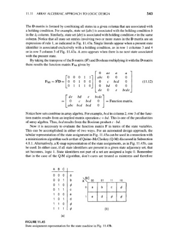
Now it is necessary to evaluate the function matrix F in terms of the state variables.
This can be accomplished in either of two ways. For an automated design approach, the
tabular representation of the state assignment in Fig. 11.45a can be used in connection with
a minimization algorithm such as that of Quine-McCluskey (Q-M) discussed in Subsection
4.8.1. Alternatively, a K-map representation of the state assignments, as in Fig. 11.45b, can
be used. In either case, if all state identifiers are present in a given state adjacency set, that
set becomes, logic 1. State identifiers not part of a set are assigned a logic 0. Remember
that in the case of the Q-M algorithm, don't cares are treated as minterms and therefore
AB C
0 0 0 a
\BC
0 0 1 b A\. 00 01 11 10
0 1 0
0 a b c
0 1 1 * c
1 0 0 e *
1 0 1 d 1 e d
* *
1 1 0 </>
1 1 1 t (b)
FIGURE 11.45
State assignment representation for the state machine in Fig. 11.43b.