
Page 568 - Engineering Digital Design
P. 568
538 CHAPTER 11 / SYNCHRONOUS FSM DESIGN CONSIDERATIONS
XY CLRREGiT
LDCNTiT
(b)
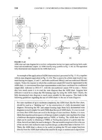
FIGURE 11.41
ASM chart and state diagram for a resolver configuration having two inputs and having both condi-
tional and unconditional outputs, (a) ASM chart by using symbols in Fig. 11.40. (b) The equivalent
fully documented state diagram for the ASM chart in (a).
An example of the application of ASM chart notation is presented in Fig. 11.4 la, together
with its state diagram equivalent in Fig. 11.41b. This is seen to be a three-state resolver seg-
ment having two inputs, X and Y, and both conditional (Mealy) and unconditional (Moore)
outputs. Notice the manner in which the conditional output RES must be represented in the
ASM chart. A conventional flowchart representation would have combined the conditional
output RES, indicated as RES if Y, with the unconditional output FIN in state c. Notice
also how much easier it is to read the state diagram than the ASM chart. Imagine how
difficult it would be to obtain the NS-forming logic by using the ASM chart. Clearly, the
fully documented state diagram is much more suitable for this purpose. This leads to the
following guidelines regarding the use of ASM charts vs the use of state diagrams:
For state machines of up to moderate complexity, the ASM chart, like the flow chart,
should be used as a "thinking tool" in the construction of a fully documented state
diagram. Extracting the NS- and output-forming logic from fully documented state
diagrams is much simpler for such FSMs than the use of ASM charts. It is rare in mod-
ern times that ASM charts are used in the design of state machines. Rather, it is more
likely that experienced designers will design modern complex state machines by using
a hardware description language such as VHDL or Verilog. The ASM chart or flow
chart can be useful in obtaining a VHDL or Verilog description of a given state ma-
chine, but will not likely be used to design it. The one notable exeption to this is the use
of the one-hot code method in state machine design, as described later in Section 13.5.
There, the ASM chart is shown to be useful in writing the NS and output functions
directly from the ASM chart without the need for K-maps or minimization algorithms.