Page 575 - Engineering Digital Design
P. 575

11.11 ARRAY ALGEBRAIC APPROACH TO LOGIC DESIGN                       545


                  which compare closely with the NS functions in Eqs. (11.11). Notice that AST+AST = AT
                  inD A.
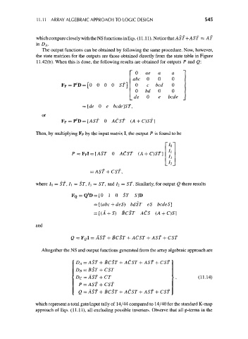
                     The output functions can be obtained by following the same procedure. Now, however,
                  the state matrices for the outputs are those obtained directly from the state table in Figure
                  11.42(b). When this is done, the following results are obtained for outputs P and Q:


                                   1
                               = P D=[0 0 0 0 Sf]
                                                           0   bd   0    0
                                                          de   0    e   bcde

                                     = [de 0 e bcde]ST,
                     or
                                   t
                            Fp = P D=[ASf 0 ACST (A + C)ST]
                  Then, by multiplying Fp by the input matrix I, the output P is found to be

                                                                       ~/o'
                                 P=F P I = [ASr 0 ACST (A + C)ST] '
                                                                        h
                                                                       A
                                        = AST + CST,

                  where 7 0 = ST, I\ = ST, 7 3 = ST, and 7 2 = ST. Similarly, for output Q there results

                                       t
                                 F Q = Q D = [0 1 0 ST    S]D
                                          = [(abc + deS) bdST eS bcdeS]
                                          = [(A + S) BCST ACS (A + C)5]


                  and

                                Q = F CI = AST + BCST + ACST + AST + CST

                    Altogether the NS and output functions generated from the array algebraic approach are

                                  D A = AST + BCST + ACST + AST + CST
                                  D B = BST + CST
                                  DC = AST + CT                                     (11-14)
                                    P = AST + CST
                                   Q = AST + BCST + ACST + AST + CST

                  which represent a total gate/input tally of 14/44 compared to 14/40 for the standard K-map
                  approach of Eqs. (11.11), all excluding possible inverters. Observe that all p-terms in the
   570   571   572   573   574   575   576   577   578   579   580