
Page 578 - Engineering Digital Design
P. 578
Sanity
A
X -
Pulse Width Adjuster X(H)
CK — (PWA) P(H)
X Synchronized in phase with
RET D flip-flops X(H)
D P(H)
3T,
1T, CK CK X(H)
2T, CK 2T, CK
P(H)
3T
CK 1T CK
(a) (b)
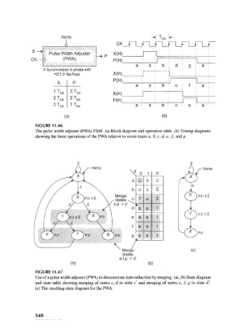
FIGURE 11.46
The pulse width adjuster (PWA) FSM. (a) Block diagram and operation table, (b) Timing diagrams
showing the three operations of the PWA relative to seven states a,b,c,d,e, f, and g.
Sanity C\ /-Sanity
X o 1 P
a (a) b 0
b d c X
Merge
/ states v c f e X
c,d -» c' ^ L
d g g 1
e a a 1
f a a 1
Pit
)P1T g a a 1
• < — I
/
^ Merc (c)
states
e,f,g -»d'
(a) " (b)
FIGURE 11.47
Use of a pulse width adjuster (PWA) to demonstrate state reduction by merging, (a), (b) State diagram
and state table showing merging of states c, d to state c' and merging of states e, f, g to state d'.
(c) The resulting state diagram for the PWA.
548