
Page 631 - Engineering Digital Design
P. 631
12.5 ASYNCHRONOUS (RIPPLE) COUNTERS 601
-c Q -c Q -c Q -C Q
n-1 2 1 0
— h—
**- '" — Q CL < >7^ Q CL < ^ Q CL <
T >-
T
T
V ? Y Y Sanity(L)
Qn ^(H) Q (H) Q,(H) Q (H)
2
B
(a)
(b)
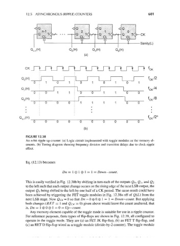
FIGURE 12.38
An n-bit ripple up-counter, (a) Logic circuit implemented with toggle modules as the memory el-
ements. (b) Timing diagram showing frequency division and transition delays due to clock ripple
effect.
Eq. (12. 13) becomes
Dn = l®l® l = l = Down-count.
This is easily verified in Fig. 12.38b by shifting in turn each of the outputs QQ, Q\, and (?2
to the left such that each output change occurs on the rising edge of the next LSB output, the
output QQ being shifted to the left by one half of a CK period. The same result could have
been achieved by triggering the FET toggle modules in Fig. 12.38a off of Q(L) from the
next LSB stage. Now Q CK = 0 so that Dn = 0 © 0 © 1 = 1 = Down— count. But applying
both changes (RET = 1 and QCK = 0) given above would leave the count unaltered, that
is, Dn = 1 © 0 © 1 = 0 = Up— count.
Any memory element capable of the toggle mode is suitable for use in a ripple counter.
For reference purposes, three types of flip-flops are shown in Fig. 12.39, all configured to
operate in the toggle mode. They are (a) an FET JK flip-flop, (b) an FET T flip-flop, and
(c) an RET D flip-flop wired as a toggle module (divide-by-2 counter). The toggle module