
Page 633 - Engineering Digital Design
P. 633
12.5 ASYNCHRONOUS (RIPPLE) COUNTERS 603
ripple counters can be cascaded to any size simply by connecting the appropriate output
from the MSB stage of one counter to the LSB clock input another, etc. For example, the
n-bit ripple counter of Fig. 12.38a can be cascaded to produce a 2n-bit up-counter by simply
connecting its Q n_\ output to the LSB FET clock input of the other n-bit ripple counter.
But remember, that ripple counter delay increases in proportion to the number of flip-flops
in the counter.
n
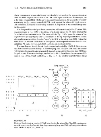
It is also possible to design a ripple counter that will count through N <2 states. This
is demonstrated in Fig. 12.40 by the design of a decade (divide-by-10) ripple counter that
is initialized into the 0000 state. The truth table in Fig. 12.40a gives the values of the
asynchronous preset (PR) and clear (CL) overrides to the flip-flops required to force a series
of asynchronous transitions from the "jump" state 1010 to the origin state 0000. Notice that
the PR and CL override values must be 0 for proper counter operation in the 10-state count
sequence. All states between state 1010 and 0000 are don't-care states.
The state diagram for this decade ripple counter is given in Fig. 12.40b. It illustrates the
fact that when the counter attempts to enter the jump state 1010 (the 11th state) the counter
will be forced to transition asynchronously through some path to the origin state 0000 (see
looped arrow). The correction logic required to do this is found from the conventional K-
map in Fig. 12.40c, which yields CL A = CL C = A • C, all other override values being
Jump state,' N
j 1010 ;
Sanity
A B C D PR ACL A PR BCL B PR CCL C PR DCL D
0 0 0 0
0 0 0 1
• -0 -
\CD
AB\ 00 01 11 10
1 0 0 1
00 0 0 0 0
7 11 t VY
1 0 1 0—jO I 0 0 0 1 0 0
1 0 1 01 0 0 0 0
0
1 1 1 ./ 10 * 0 J 1
0 0 0 0 0 0 0 0 0 0 0 0 CL A = CL C = AC
(a) (b) (c)
FIGURE 12.40
Design of decade ripple up-counter, (a) Truth table showing the values of the PR and CL asynchronous
override inputs to the flip-flops, (b) State diagram showing jump state 1010. (c) K-map and minimum
cover for the CL inputs, CL& and CLc-