
Page 638 - Engineering Digital Design
P. 638
608 CHAPTER 12 / MODULE AND BIT-SLICE DEVICES
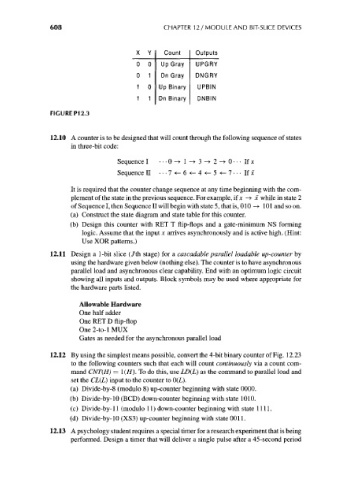
X Y Count Outputs
0 0 Up Gray UPGRY
0 1 Dn Gray DNGRY
1 0 Up Binary UPBIN
1 1 Dn Binary DNBIN
FIGURE P12.3
12.10 A counter is to be designed that will count through the following sequence of states
in three-bit code:
Sequence I •••0-»l-»3-»2-*0---Ifj c
Sequence II •••7«-6«-4«-5«-7---If f
It is required that the counter change sequence at any time beginning with the com-
plement of the state in the previous sequence. For example, if jc -> x while in state 2
of Sequence I, then Sequence II will begin with state 5, that is, 010 —> 101 and so on.
(a) Construct the state diagram and state table for this counter.
(b) Design this counter with RET T flip-flops and a gate-minimum NS forming
logic. Assume that the input x arrives asynchronously and is active high. (Hint:
Use XOR patterns.)
12.11 Design a 1-bit slice (/th stage) for a cascadable parallel loadable up-counter by
using the hardware given below (nothing else). The counter is to have asynchronous
parallel load and asynchronous clear capability. End with an optimum logic circuit
showing all inputs and outputs. Block symbols may be used where appropriate for
the hardware parts listed.
Allowable Hardware
One half adder
One RET D flip-flop
One2-to-lMUX
Gates as needed for the asynchronous parallel load
12.12 By using the simplest means possible, convert the 4-bit binary counter of Fig. 12.23
to the following counters such that each will count continuously via a count com-
mand CNT(H) = !(//). To do this, use LD(L) as the command to parallel load and
set the CL(L) input to the counter to 0(L).
(a) Divide-by-8 (modulo 8) up-counter beginning with state 0000.
(b) Divide-by-10 (BCD) down-counter beginning with state 1010.
(c) Divide-by-11 (modulo 11) down-counter beginning with state 1111.
(d) Divide-by-10 (XS3) up-counter beginning with state 0011.
12.13 A psychology student requires a special timer for a research experiment that is being
performed. Design a timer that will deliver a single pulse after a 45-second period