Page 640 - Engineering Digital Design
P. 640

610                             CHAPTER 12 / MODULE AND BIT-SLICE DEVICES


                                                                             p
                                                                             r
                                                                              B
                                                                     S
                                                                      o                   CL 0-
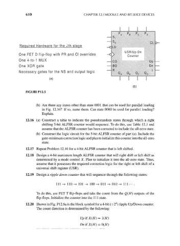
                  Required Hardware for the Jth stage             -c LD
                                                                            USR/Up-Dn
                 One FET D flip-flop with PR and Cl overrides     -c          Counter
                 One 4-to-1 MUX
                                                                     CO                   Up
                 One XOR gate                                        80                   Dn
                                                                     R                     L
                  Necessary gates for the NS and output logic
                                  (   a   )                              I    I    I

                                                                                 (b)
                     FIGURE P12.5


                          (b) Are there any states other than state 0001 that can be used for parallel loading
                              in Fig. 12.34? If so, name them. Can state 0000 be used for parallel loading?
                              Explain.
                     12.16 (a) Construct a table to indicate the pseudorandom states through which a right
                              shifting 5-bit ALFSR counter would sequence. To do this, use Table 12.1 and
                              assume that the ALFSR counter has been corrected to include the all-zero state.
                          (b) Construct the logic circuit for the 5-bit ALFSR counter of part (a). Include the
                              gate-minimum correction logic and plan to initialize this counter into the all-zero
                              state.
                     12.17 Repeat Problem 12. 16 for a 4-bit ALFSR counter that is left shifted.

                     12.18 Design a 4-bit maximum length ALFSR counter that will right shift or left shift as
                           determined by a mode control X. Plan to initialize it into the all-zero state. Thus,
                           assume that it possesses the required correction logic for the right or left shift of a
                           universal shift register (USR).

                     12.19 Design a ripple down-counter that will sequence through the following states:

                                     111 -> 110 -> 101 -> 100 -* Oil -> 010 -> 111 • • • .

                           To do this, use FET T flip-flops and take the count from the Q(H) outputs of the
                           flip-flops. Initialize the counter into the 111 state.
                                                                       4
                     12.20 Shown in Fig. P12.6a is the block symbol for a 4-bit (-^2 ) ripple Up/Down counter.
                           The count direction is determined by the following:

                                                   UpifX(H)=
                                                   Dn if X(H) = 0(H)
   635   636   637   638   639   640   641   642   643   644   645