
Page 641 - Engineering Digital Design
P. 641
PROBLEMS 611
CK
4-Bit Ripple Up/Dn Required Hardware
v/u . u
X(H)
—H counter
Four FET D flip-flops
Four 2-to-1 MUXs
Q A (H) Q B(H) Q C (H) Q D (H)
(a) (b)
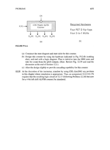
FIGURE P12.6
(a) Construct the state diagram and state table for this counter.
(b) Design this counter by using the hardware indicated in Fig. P12.6b (nothing
else), and end with a logic diagram. Plan to initialize into the 0000 state and
take the count from the Q(H) outputs. (Hint: Review Fig. 12.39 and read the
discussion at the end of Section 12.5.)
(c) Alter the design slightly to provide cascading capability for this counter.
12.21 At the discretion of the instructor, simulate by using EXL-Sim2002 any problem
in this chapter where simulation is appropriate. Thus, an assignment 12.21/12.17b
requires that the resulting logic circuit of 12.17 (following Problem 12.16b but now
for a 4-bit left shift ALFSR counter) be simulated.