
Page 634 - Engineering Digital Design
P. 634
604 CHAPTER 12 / MODULE AND BIT-SLICE DEVICES
Q A (H) Q B (H) Q C (H) Q D (H)
T
< QAT <y- -c Q T y- -c Q C < s — CK
i B < 1 — Q D
Q Q i Q
CL CL CL CL
v Y
^ A
/ \
'"rtrr'
- \-f\- Sanity(L)
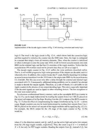
FIGURE 12.41
Implementation of the decade ripple counter of Fig. 12.40 showing correction and sanity logic.
logic 0. The result is the logic circuit in Fig. 12.41, which shows both the correction logic
and that required to initialize the counter into the 0000 state. Here, this logic is configured
in a manner that simply clears all memory elements. Thus, when the counter is initialized
or when it attempts to enter the jump state 1010, it will be forced asynchronously into state
0000 via the external logic and the four CL overrides of the toggle modules. Notice that the
asynchronous PR overrides need not be present since they are all set at logic 0.
The decade ripple counter in Fig. 12.41 suffers the same problems described earlier.
That is, it will exhibit progressive logic noise generation if the outputs are decoded, and it is
inherently slow. In addition, this counter breaks the 2" count, thereby requiring it to undergo
an asynchronous transition from the 1010 state to the origin state 0000 via the asynchronous
CL overrides. But this can occur only after a delay through the external and internal logic
associated with CL. Consequently, additional timing problems can be created if an attempt
is made to decode the output signals. Therefore, as a rule of thumb, it is advisable to use
ripple counters in the absence of any output decoding logic. This rule is especially important
if the decoded signals are used as inputs to other switching devices. The few exceptions to
this rule were noted earlier.
Synchronous unidirectional binary counters, such as the cascadable BCD up-counter in
Fig. 12.17a, can be made bidirectional by reading the outputs from 2-to-l MUXs placed on
the mixed-rail outputs of its flip-flops. Reading from the Q(L) outputs of the BCD counter in
Fig. 12.11 a has the effect of complementing the output waveforms in Fig. 12.18 — a down
count. Ripple counters can also be made bidirectional by reading their outputs from 2-to-l
MUXs placed on the mixed-rail outputs of the toggle modules and by applying Eq. (12.13).
For example, the MUX output for the Jth stage of the ripple counter in Fig. 12.38a
would be
Yj = XQj+XQj, (12.16)
where X is the direction control, and Qj and Qjare the active high and active low outputs
from the Jth stage toggle module, respectively. Thus, the count is up if X = 1 or down if
X = 0, but only for FET toggle modules. Reading the outputs from Qj instead of Qj has