
Page 628 - Engineering Digital Design
P. 628
598 CHAPTER 12 / MODULE AND BIT-SLICE DEVICES
\CD
AB\ 00 01 11 10
00 0(H)-
P P P P
01 r A * B r C * D
0(H)
11 S o USR CL •Sanity(L)
CK
10 R -0(H)
Q A Q B Q c
A(H) B(H) C(H) D(H)
(a) (b)
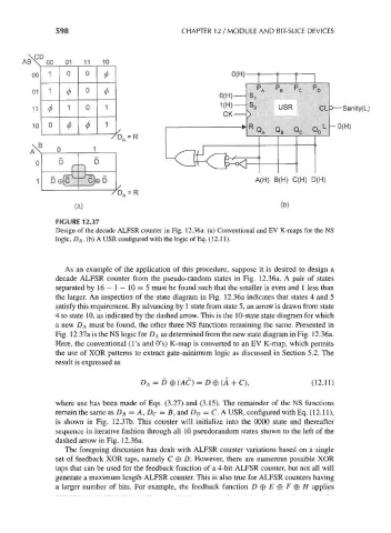
FIGURE 12.37
Design of the decade ALFSR counter in Fig. 12.36a. (a) Conventional and EV K-maps for the NS
logic, D A. (b) A USR configured with the logic of Eq. (12.11).
As an example of the application of this procedure, suppose it is desired to design a
decade ALFSR counter from the pseudo-random states in Fig. 12.36a. A pair of states
separated by 16— 1 — 10 = 5 must be found such that the smaller is even and 1 less than
the larger. An inspection of the state diagram in Fig. 12.36a indicates that states 4 and 5
satisfy this requirement. By advancing by 1 state from state 5, an arrow is drawn from state
4 to state 10, as indicated by the dashed arrow. This is the 10-state state diagram for which
a new D A must be found, the other three NS functions remaining the same. Presented in
Fig. 1231 a. is the NS logic for D A as determined from the new state diagram in Fig. 12.36a.
Here, the conventional (1's and O's) K-map is converted to an EV K-map, which permits
the use of XOR patterns to extract gate-minimum logic as discussed in Section 5.2. The
result is expressed as
D A = D0(AC) = D®(A+C), (12.11)
where use has been made of Eqs. (3.27) and (3.15). The remainder of the NS functions
remain the same as D B = A, D c = B, and D D = C. A USR, configured with Eq. (12.11),
is shown in Fig. 12.37b. This counter will initialize into the 0000 state and thereafter
sequence in iterative fashion through all 10 pseudorandom states shown to the left of the
dashed arrow in Fig. 12.36a.
The foregoing discussion has dealt with ALFSR counter variations based on a single
set of feedback XOR taps, namely C © D. However, there are numerous possible XOR
taps that can be used for the feedback function of a 4-bit ALFSR counter, but not all will
generate a maximum length ALFSR counter. This is also true for ALFSR counters having
a larger number of bits. For example, the feedback function D © E © F 0 H applies