
Page 625 - Engineering Digital Design
P. 625
CD \CD
AB\ 00 01 11 10 AB\ 00 01 11 10 0(H)
00 00
P A P B P c
*1
01 01
»o USR Sanity(L)
CK-
11 11
0(H)- /
<Q A Q B Q c
10 10
S = AD L = A
0
A(H) B(H) C(H) D(H)
(a) (b) (c)
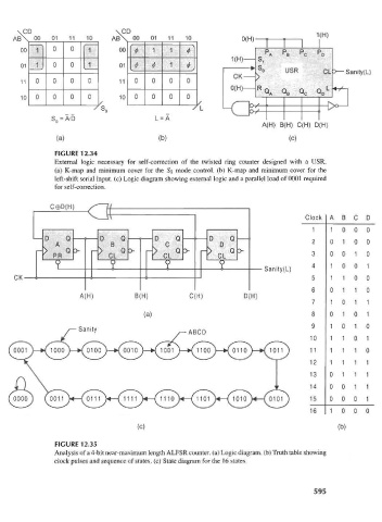
FIGURE 12.34
External logic necessary for self-correction of the twisted ring counter designed with a USR.
(a) K-map and minimum cover for the So mode control, (b) K-map and minimum cover for the
left-shift serial input, (c) Logic diagram showing external logic and a parallel load of 0001 required
for self-correction.
C®D(H) f It
Clock A B C D
1 100 0
D Q D Q D Q D Q 2 010 0
A B C D
— > — > — > — > 3 001 0
>PR ° >CL ° >CL ° >CL °
V Y Y Y Sanity(L) 4 1 0 0 1
CK 5 1 1 0 0
6 0 1 1 0
A(H) B(H) C(H) D(H)
1 0 1 1
(a) 8 010 1
1 0 1 0
Sanity /-ABCD 9
10 1 1 0 1
11 1 1 1 0
12 1 1 1 1
13 0 1 1 1
14 0 0 1 1
15 000 1
16 1 0 0 0
(c) (b)
FIGURE 12.35
Analysis of a 4-bit near-maximum length ALFSR counter, (a) Logic diagram, (b) Truth table showing
clock pulses and sequence of states, (c) State diagram for the 16 states.
595