
Page 624 - Engineering Digital Design
P. 624
594 CHAPTER 12 / MODULE AND BIT-SLICE DEVICES
A B C D ! D A D B D c D D
-T7- U 0 0 1
Sanity^. 0 0 0 1 -^ 0 0 1 1
0 0 1 1 -p7 0 1 1 1
0 1 1 1 -J7- 1 1 1 1
1 1 1 1 - . 1 1 1 0
1 1 1 0 ^ 1 1 0 0
1 1 0 0 - 100 0
1000-f^OOO O
o o o o !
(b)
\CD
AB\ 00 01 11 10
00
Si
01 0(H) Universal Shift
CK )> Register CL Sanity(L)
11
0(H) Q,
Q A Q B Q r
10
L = A
( C) A(H) B(H) C(H) D(H)
(d)
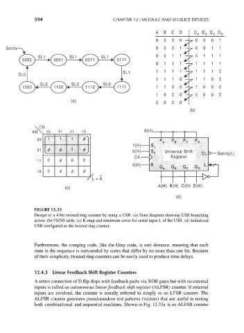
FIGURE 12.33
Design of a 4-bit twisted ring counter by using a USR. (a) State diagram showing USR branching
action, (b) PS/NS table, (c) K-map and minimum cover for serial input L of the USR. (d) Initialized
USR configured as the twisted ring counter.
Furthermore, the creeping code, like the Gray code, is unit distance, meaning that each
state in the sequence is surrounded by states that differ by no more than one bit. Because
of their simplicity, twisted ring counters can be easily used to produce time delays.
12.4.3 Linear Feedback Shift Register Counters
A series connection of D flip-flops with feedback paths via XOR gates but with no external
inputs is called an autonomous linear feedback shift register (ALFSR) counter. If external
inputs are involved, the counter is usually referred to simply as an LFSR counter. The
ALFSR counter generates pseudorandom test patterns (vectors) that are useful in testing
both combinational and sequential machines. Shown in Fig. 12.35a is an ALFSR counter