
Page 619 - Engineering Digital Design
P. 619
12.3 SYNCHRONOUS BINARY COUNTERS 589
2. Data inputs that are asynchronously loaded never have to be synchronized with clock
since the loading process interrupts the operation of the flip-flops by temporarily intro-
ducing a clear or preset condition into the flip-flops. Data inputs that are synchronously
loaded should be synchronized with clock for reasons discussed in Subsection 11.4.4.
Generally, the cost in hardware of asynchronous parallel loading will be somewhat
greater than that for synchronous parallel loading. Comparing Figs. 12.26a and 12.28c is
indicative of a small difference in the external logic to the D flip-flop, two gates per stage
including the 2-to-l MUX. Speedwise there is little difference between the two means of
parallel loading. The choice of flip-flop type (e.g., T or D or JK) can be a more significant
factor in both hardware and speed. However, these factors may be unimportant if the register
or counter is implemented by using an array logic device such as a V-type PAL or Xilinx
4000 series FPGA. These devices have built-in D flip-flops, SSI devices, and a host of
other features of which use can be made. But such devices will usually require the use of
proprietary software to program them, as discussed in Section 7.8.
12.3.7 Branching Action of a 4-Bit Parallel Loadable Up/Down Counter
In Section 13.4 a parallel loadable up/down counter is used as the memory in state machine
design — an alternative architecture. To program the counter in such applications, it is
necessary to specify the branching action of the counter for each state-to-state transition in
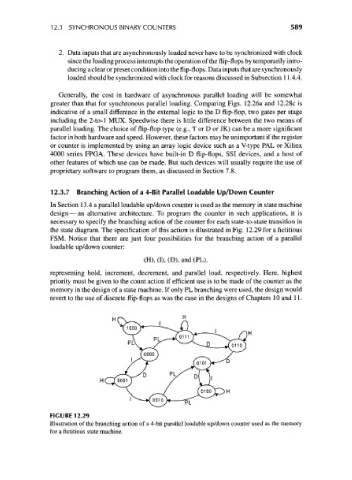
the state diagram. The specification of this action is illustrated in Fig. 12.29 for a fictitious
FSM. Notice that there are just four possibilities for the branching action of a parallel
loadable up/down counter:
(H), (I), (D), and (PL),
representing hold, increment, decrement, and parallel load, respectively. Here, highest
priority must be given to the count action if efficient use is to be made of the counter as the
memory in the design of a state machine. If only PL branching were used, the design would
revert to the use of discrete flip-flops as was the case in the designs of Chapters 10 and 11.
FIGURE 12.29
Illustration of the branching action of a 4-bit parallel loadable up/down counter used as the memory
for a fictitious state machine.