
Page 615 - Engineering Digital Design
P. 615
12.3 SYNCHRONOUS BINARY COUNTERS 585
D/U Q, Cl CNT CO D/Q^oo 01 11 10
Increment
(Up count)
'CNT,
_\QjCI
D/U X 00 01 11 10
Decrement
(Dn count)
CO,
(a) (b)
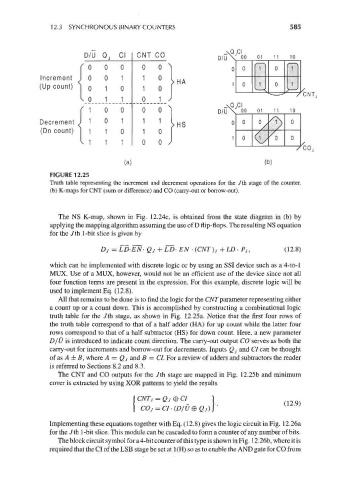
FIGURE 12.25
Truth table representing the increment and decrement operations for the 7th stage of the counter,
(b) K-maps for CNT (sum or difference) and CO (carry-out or borrow-out).
The NS K-map, shown in Fig. 12.24c, is obtained from the state diagram in (b) by
applying the mapping algorithm assuming the use of D flip-flops. The resulting NS equation
for the Jth 1-bit slice is given by
Dj = LD-EN- Qj + LD- EN -(CNT)j + LD • Pj, (12.8)
which can be implemented with discrete logic or by using an SSI device such as a 4-to-l
MUX. Use of a MUX, however, would not be an efficient use of the device since not all
four function terms are present in the expression. For this example, discrete logic will be
used to implement Eq. (12.8).
All that remains to be done is to find the logic for the CNT parameter representing either
a count up or a count down. This is accomplished by constructing a combinational logic
truth table for the /th stage, as shown in Fig. 12.25a. Notice that the first four rows of
the truth table correspond to that of a half adder (HA) for up count while the latter four
rows correspond to that of a half subtracter (HS) for down count. Here, a new parameter
D/U is introduced to indicate count direction. The carry-out output CO serves as both the
carry-out for increments and borrow-out for decrements. Inputs Qj and Cl can be thought
of as A ± B, where A = Qj and B = CL For a review of adders and subtracters the reader
is referred to Sections 8.2 and 8.3.
The CNT and CO outputs for the /th stage are mapped in Fig. 12.25b and minimum
cover is extracted by using XOR patterns to yield the results
COj=CI-(D/U®Qj} '
Implementing these equations together with Eq. (12.8) gives the logic circuit in Fig. 12.26a
for the 7th 1-bit slice. This module can be cascaded to form a counter of any number of bits.
The block circuit symbol for a 4-bit counter of this type is shown in Fig. 12.26b, where itis
required that the Cl of the LSB stage be set at 1 (H) so as to enable the AND gate for CO from