
Page 614 - Engineering Digital Design
P. 614
584 CHAPTER 12 / MODULE AND BIT-SLICE DEVICES
with asynchronous preset and clear overrides built into them. Implementation of this counter
by using FPGA-type devices will require special programming software.
The cascadable up/down binary counter in Figs. 12.22 and 12.23 can be designed with
asynchronous parallel load capability while retaining the true hold feature. To do this
simply requires that the synchronous parallel load feature be removed from the operation
table in Fig. 12.22a, and then applied as an asynchronous parallel load via the PRE and
CLR overrides of each D flip-flop, as is done in Fig. 12.20. Now, only one mode control
remains (S), permitting the use of a 2-to-l MUX to implement the new Dj function. With
a few changes, the bidirectional 4-bit counter in Fig. 12.23 is equivalent to the commercial
74xxl69 counter.
12.3.5 One-Bit Modular Design of Parallel Loadable Up/Down
Counters with True Hold
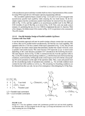
A one-bit modular approach will now be used to design a binary counter that can count up
or down, that can be parallel loaded synchronously, and that has true hold capability. The
operation table for a 1-bit slice counter of this type is presented in Fig. 12.24a. The LD and
EN inputs are the mode control inputs that determine whether the counter will hold, count
or parallel load synchronously. The count function CNT represents an up- or down-count
depending on the count direction parameter D/U introduced in the following discussion.
The state diagram, shown in Fig. 12.24b, is constructed directly from the operation table in
Fig. 12.24a. For example, the branching condition f ab is the Boolean sum of all set producing
conditions, each formed by ANDing the mode control inputs on the left with the correspond-
ing NS action parameter on the right of the operation table. Thus, count and parallel load
are the set-producing modes of operation that constitute f ab. The set hold condition must
contain the true hold condition as well as f ab. The remaining two branching conditions can
be obtained from the sum rule, but are of no consequence when designing for D flip-flops.
LD EN NSj
0 0 Qj True Hold f ab = LD-EN(CNT) J+ , _ Q
0 1 (CNT)j Count
1
1 X Pj Parallel Load
LD = Parallel load command ~> DJ = LD-EN-QJ + f ab
EN = Count enable command
(b)
FIGURE 12.24
Design of a 1-bit slice up/down counter with synchronous parallel load and true hold capability,
(a) Operation table, (b) State diagram for the /th stage, (c) K-map and minimum cover for the 7th
stage assuming the use of D flip-flops.