
Page 611 - Engineering Digital Design
P. 611
12.3 SYNCHRONOUS BINARY COUNTERS 581
4k-Parallel load inputs
p p p p p p p
r A r B r C r D P 4 Pa P, Pr r A * B r C
CL CL CL
> >
k-1
CO Up CO Up CO Up«--Up(H)
BO Dn BO Dn BO Dn«—Dn(H)
Q Q Q Q Q 4 Q B Q n Q n Q
CL(L)
MSB LSB
\ ^ x X
\x
4k
2 -1 Count
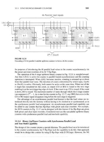
FIGURE 12.21
Cascading of 4-bit parallel loadable up/down counters to form a 4fc-bit counter.
for purposes of introducing the 4k parallel load values to the counter asynchronously via
the preset and clear overrides of its 4k T flip-flops.
The operation of the fc-stage up/down binary counter in Fig. 12.21 is straightforward.
Any time LD(L) is active the counter is parallel loaded asynchronously and the counting
operation is interrupted. When LD(L) becomes inactive, counting is resumed up or down
from that parallel load value. The direction of count is determined by which input, Up(H)
or Dn(H\ is active. Obviously, both cannot be active at the same time. When one of the
k stages has completed its full count, an output (CO or BO) is issued to the next stage
enabling it on the next triggering edge of clock. If the count is up, CO is issued; if the count
is down, BO is issued. The maximum number of states through which this fc-stage counter
4k
can sequence is 2 — 1. As is true for the counter in Fig. 12.17, any ORG that exists in the
CO or BO output signal disappears long before the next stage is triggered.
The advantage of an asynchronous parallel load feature is that the load values are in-
troduced directly into the memory without having to be clocked in or synchronized, as in
the synchronous parallel load arrangement. An asynchronous parallel load capability can
be added to any counter that has flip-flops with preset and clear overrides. For example,
the BCD counters in Fig. 12.17 can be designed with this feature if the flip-flops are given
both preset and clear input overrides. Considered next are the cascadable up/down binary
counters with synchronous parallel load and true hold capability.
12.3.4 Binary Up/Down Counters with Synchronous Parallel Load
and True Hold Capability
The design of this counter creates a special dilemma. The parallel load must be introduced
to the counter synchronously, but T flip-flops lack the capability to do this. One approach
would be to design this counter by using D flip-flops with D NS logic. However, the NS