
Page 608 - Engineering Digital Design
P. 608
II
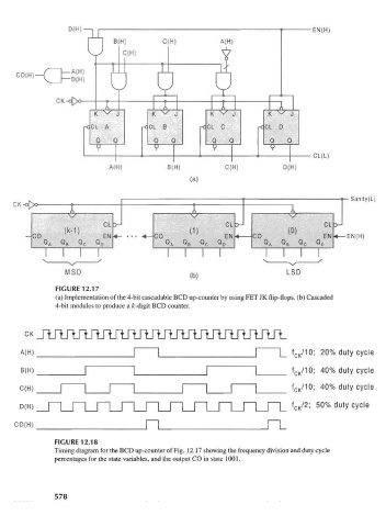
D(H)—| • EN(H)
B(H) C(H) A(H)
vJ C(H) Y
o
1 JL A
A H
CO(H)—C — ( )
T
CK-o[>o M r^
T A A A
K ^ J K X/ I t^ X/ J K ^/ J
l\ v
U
rCCL A rCCL B rCCL C -c CL D
Q Q Q Q Q Q Q Q
V V V
^ CL(L)
A(H) B(H) C(H) D(H)
(a)
Sanity(L)
A A
->_
CL CL -y_ CL -y_
CO ^ EN <«- ... <«-CO EN 4 CO <°> EN 4— EN(H)
QA QB QC QO QA Q 8 QC QQ
MSD (b) LSD
FIGURE 12.17
(a) Implementation of the 4-bit cascadable BCD up-counter by using FET JK flip-flops, (b) Cascaded
4-bit modules to produce a A>digit BCD counter.
A(H) _ | | _ | |_ f CK/10; 20% duty cycle
/1
B(H) _ [ | _ | | _ f C K °: 40% duty cycle
1 40% dut c cle
W °; v v
FIGURE 12.18
Timing diagram for the BCD up-counter of Fig. 12.17 showing the frequency division and duty cycle
percentages for the state variables, and the output CO in state 1001.
578