
Page 605 - Engineering Digital Design
P. 605
12.3 SYNCHRONOUS BINARY COUNTERS 575
\B \ B 1
A\ 0 1 A\ 0
0 0 1 0 1 1
1 0 1 1 1 1
/
-7T A = B ZT B = 1
(a) (b)
CK
r~ CK
\ ' T \/ r
QA<H>
A B
Q Q Q Q
V V
Q A(H) Q B(H)
(c) (d)
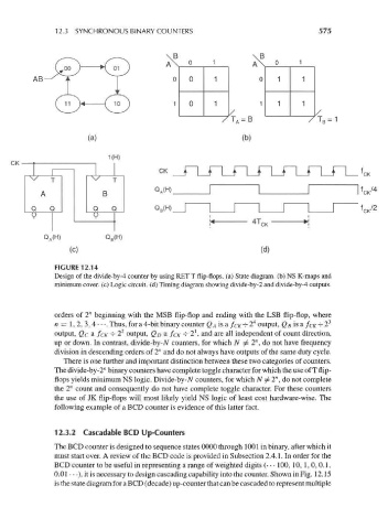
FIGURE 12.14
Design of the divide-by-4 counter by using RET T flip-flops, (a) State diagram, (b) NS K-maps and
minimum cover, (c) Logic circuit, (d) Timing diagram showing divide-by-2 and divide-by-4 outputs.
orders of 2" beginning with the MSB flip-flop and ending with the LSB flip-flop, where
4 3
n = 1, 2, 3, 4 • • •. Thus, for a 4-bit binary counter Q A is a f CK -=- 2 output, Q B is a /CK -^ 2
2
1
output, Qc a fcK -^ 2 output, Q D a /CK -^- 2 , and are all independent of count direction,
up or down. In contrast, divide-by-N counters, for which N / 2", do not have frequency
division in descending orders of 2" and do not always have outputs of the same duty cycle.
There is one further and important distinction between these two categories of counters.
The divide-by-2" binary counters have complete toggle character for which the use of T flip-
n
flops yields minimum NS logic. Divide-by-N counters, for which N ^2 ,do not complete
the 2" count and consequently do not have complete toggle character. For these counters
the use of JK flip-flops will most likely yield NS logic of least cost hardware-wise. The
following example of a BCD counter is evidence of this latter fact.
12.3.2 Cascadable BCD Up-Counters
The BCD counter is designed to sequence states 0000 through 1001 in binary, after which it
must start over. A review of the BCD code is provided in Subsection 2.4.1. In order for the
BCD counter to be useful in representing a range of weighted digits (• • • 100, 10, 1, 0, 0.1,
0.01 • • •), it is necessary to design cascading capability into the counter. Shown in Fig. 12.15
is the state diagram for a BCD (decade) up-counter that can be cascaded to represent multiple