
Page 604 - Engineering Digital Design
P. 604
574 CHAPTER 12 / MODULE AND BIT-SLICE DEVICES
Q AQ B = AB
(a) (b)
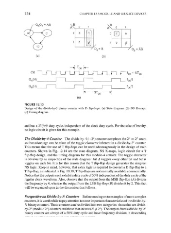
FIGURE 12.13
Design of the divide-by-3 binary counter with D flip-flops, (a) State diagram, (b) NS K-maps.
(c) Timing diagram.
and has a 33'/3% duty cycle, independent of the clock duty cycle. For the sake of brevity,
no logic circuit is given for this example.
2
2
The Divide-by-4 Counter The divide-by-4 O2 ) counter completes the 2" = 2 count
so that advantage can be taken of the toggle character inherent in a divide-by-2" counter.
This means that the use of T flip-flops can be used advantageously in the design of such
counters. Shown in Fig. 12.14 are the state diagram, NS K-maps, logic circuit for a T
flip-flop design, and the timing diagram for this modulo-4 counter. The toggle character
is obvious by an inspection of the state diagram: bit A toggles every other bit and bit B
toggles on each bit. It is for this reason that the T flip-flop design generates the simplest
NS logic. Keep in mind, however, that extra logic is required to convert a D flip-flop to a
T flip-flop, as indicated in Fig. 10.39; T flip-flops are not normally available commercially.
Notice that the outputs each exhibit a duty cycle of 50% independent of the duty cycle of the
regular clock waveform. Also, observe that the output from the MSB flip-flop (A) divides
the frequency by 4, whereas the output from the LSB flip-flop (B) divides it by 2. This fact
will be expanded upon in the discussion that follows.
Perspective on Divide-by-N Counters Before moving on to examples of more complex
counters, it is worth while to pay attention to some important characteristics of the divide-by -
N binary counters. These counters can be divided into two categories: those that are divide-
by-2" (modulo 2") counters and those that are not (N ^ 2"). The outputs from a divide-by-2"
binary counter are always of a 50% duty cycle and have frequency division in descending