
Page 617 - Engineering Digital Design
P. 617
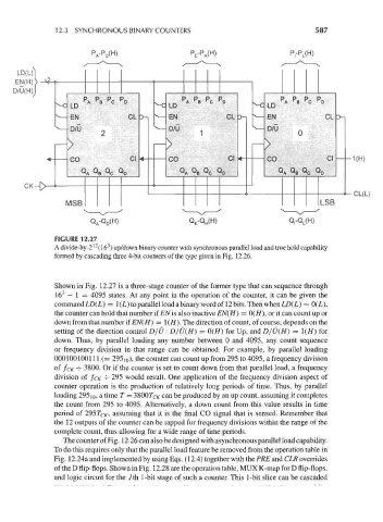
12.3 SYNCHRONOUS BINARY COUNTERS                                     587


                            P A-P D(H)               P E-PH(H)                 P,-P L(H)


                         P P P P
                         r A  r B  r C  r D
                       n


          CK-[>
                                                                                                CL(L)


                           Q A-Q D(H)
                  FIGURE 12.27
                                3
                            12
                  A divide-by-2 (16 ) up/down binary counter with synchronous parallel load and true hold capability
                  formed by cascading three 4-bit counters of the type given in Fig. 12.26.


                  Shown in Fig. 12.27 is a three-stage counter of the former type that can sequence through
                    3
                  16  — 1 = 4095 states. At any point in the operation of the counter, it can be given the
                  command L£>(L) = 1(L) to parallel load a binary word of 12 bits. Then when LD(L) = 0(L),
                  the counter can hold that number if EN is also inactive EN(H) = 0(//), or it can count up or
                  down from that number if EN(H) = !(//). The direction of count, of course, depends on the
                  setting of the direction control D/U: D/U(H) = 0(H) for Up, and D/U(H} - \(H} for
                 down. Thus, by parallel loading any number between 0 and 4095, any count sequence
                 or frequency division in that range can be obtained. For example, by parallel loading
                 000100100111 (= 29510), the counter can count up from 295 to 4095, a frequency division
                 of fcic -j- 3800. Or if the counter is set to count down from that parallel load, a frequency
                 division of f CK -=- 295 would result. One application of the frequency division aspect of
                 counter operation is the production of relatively long periods of time. Thus, by parallel
                 loading 295 10, a time T = 38007c/r can be produced by an up count, assuming it completes
                 the count from 295 to 4095. Alternatively, a down count from this value results in time
                 period of 295 TCK, assuming that it is the final CO signal that is sensed. Remember that
                 the 12 outputs of the counter can be tapped for frequency divisions within the range of the
                 complete count, thus allowing for a wide range of time periods.
                    The counter of Fig. 12.26 can also be designed with asynchronous parallel load capability.
                 To do this requires only that the parallel load feature be removed from the operation table in
                 Fig. 12.24a and implemented by using Eqs. (12.4) together with the PRE and CLR overrides
                 of the D flip-flops. Shown in Fig. 12.28 are the operation table, MUX K-map for D flip-flops,
                 and logic circuit for the /th 1-bit stage of such a counter. This 1-bit slice can be cascaded