
Page 621 - Engineering Digital Design
P. 621
12.4 SHIFT-REGISTER COUNTERS 591
A B C D ! D A D B D C D D
Sanity^ r-ABCD = Q AQ BQ CQ D 0001-^001 0 n R
\ / y U A = b
0010-^010 0 D = C
0 1 0 0 -7 1 0 0 0 D=D
c
1 0 0 0 -hr 0 0 0 1
*f
0001 !
(a) (b)
Q A(H) Q B(H) Q C(H) Q D(H)
DJ
t
-Q D Q D Q D Q
A 4 B J c > D .
<Q -c -c Q -c
C L < °CL < C L < %R <
V ¥ V Sanity(L)
CK '
(d)
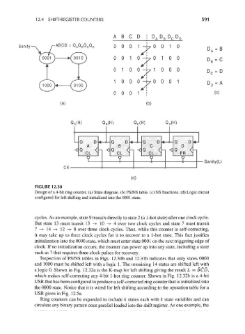
FIGURE 12.30
Design of a 4-bit ring counter, (a) State diagram, (b) PS/NS table, (c) NS functions, (d) Logic circuit
configured for left shifting and initialized into the 0001 state.
cycles. As an example, state 9 transits directly to state 2 (a 1-hot state) after one clock cycle.
But state 13 must transit 13 -> 10 -> 4 over two clock cycles and state 1 must transit
1 —> 14 -+ 12 —> 8 over three clock cycles. Thus, while this counter is self-correcting,
it may take up to three clock cycles for it to recover to a 1-hot state. This fact justifies
initialization into the 0000 state, which must enter state 0001 on the next triggering edge of
clock. If no initialization occurs, the counter can power up into any state, including a state
such as 1 that requires three clock pulses for recovery.
Inspection of PS/NS tables in Figs. 12.30b and 12.3 Ib indicates that only states 0000
and 1000 must be shifted left with a logic 1. The remaining 14 states are shifted left with
a logic 0. Shown in Fig. 12.32a is the K-map for left shifting giving the result L = BCD,
which makes self-correcting any 4-bit 1-hot ring counter. Shown in Fig. 12.32b is a 4-bit
USR that has been configured to produce a self-corrected ring counter that is initialized into
the 0000 state. Notice that it is wired for left shifting according to the operation table for a
USR given in Fig. 12.5a.
Ring counters can be expanded to include k states each with k state variables and can
circulate any binary pattern once parallel loaded into the shift register. As one example, the