
Page 622 - Engineering Digital Design
P. 622
Non-self-correcting
PS NS Decimal
A B C D D A D B D c D D RL PS NS
000 0 0 0 0 0 R L 0 -> 0 Hang state 0 -* 1 SL 1
0 0 1 1 0 1 1 0 R L 3 -» 6 3 -» 6 SL O
0 1 0 1 1 0 1 0 RL 5 -» 10 5 -» 10 SLO
0 1 1 0 1 1 0 0 RL 6 -» 12 6 -^ 12 SLO
0 1 1 1 1 1 1 0 RL 7 -» 14 7 -» 14 SLO
1 0 0 1 0 0 1 1 R L 9 -* 3 9^ 2 SL O
1 0 1 0 0 1 0 1 RL 10 -» 5 10 -> 4 SLO
101 1 0 1 1 1 RL 11 -» 7 11 -> 6 SLO
1 1 0 0 1 0 0 1 RL 12 -» 9 12 ^ 8 SLO
1 1 0 1 1 0 1 1 RL 13 -» 11 13 -» 10 SLO
1 1 1 0 1 1 0 1 RL 14 -» 13 14 -» 12 SLO
1 1 1 1 1 1 1 1 R L 1 5 -» 1 5 Hang state 1 5 -» 1 4 SL O
RL = Rotate left SL = Shift left
(a) (b)
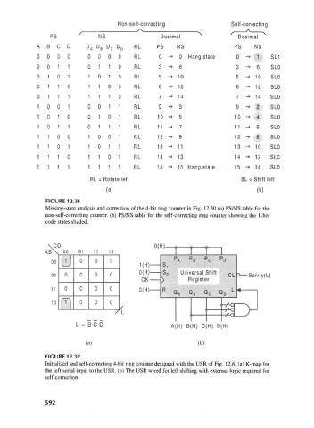
FIGURE 12.31
Missing-state analysis and correction of the 4-bit ring counter in Fig. 12.30 (a) PS/NS table for the
non-self-correcting counter, (b) PS/NS table for the self-correcting ring counter showing the 1-hot
code states shaded.
\CD 0(H).
AB\ 00 01 11 10
00
v—/ | I I I i^n; 1 o 1
0(H) Universal Shift
01 CL 3—Sanity(L)
CK- Register
11 0(H)
m
10 0 0
L = B-C-D A(H) B(H) C(H) D(H)
(a) (b)
FIGURE 12.32
Initialized and self-correcting 4-bit ring counter designed with the USR of Fig. 12.6. (a) K-map for
the left serial input to the USR. (b) The USR wired for left shifting with external logic required for
self-correction.
592