
Page 627 - Engineering Digital Design
P. 627
12.4 SHIFT-REGISTER COUNTERS 597
(a)
0(H).
P C
01 11 10 0(H)-
o USR CL •Sanity(L)
00
CK
L
01 0(H)
Q A Q B Q c Q D
11
10 1
V
D A = R
A(H) B(H) C(H) D(H)
(b) (c)
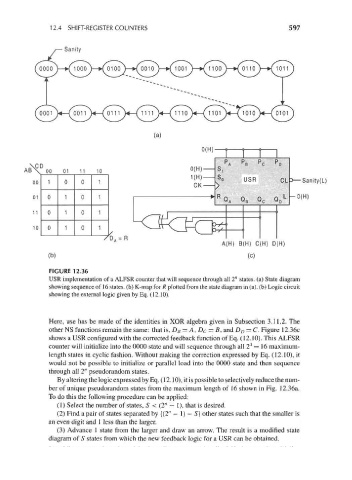
FIGURE 12.36
USR implementation of a ALFSR counter that will sequence through all 2" states, (a) State diagram
showing sequence of 16 states, (b) K-map for R plotted from the state diagram in (a), (b) Logic circuit
showing the external logic given by Eq. (12.10).
Here, use has be made of the identities in XOR algebra given in Subsection 3.11.2. The
other NS functions remain the same: that is, D B = A, D c = B, and D D = C. Figure 12.36c
shows a USR configured with the corrected feedback function of Eq. (12.10). This ALFSR
4
counter will initialize into the 0000 state and will sequence through all 2 = 16 maximum-
length states in cyclic fashion. Without making the correction expressed by Eq. (12.10), it
would not be possible to initialize or parallel load into the 0000 state and then sequence
through all 2" pseudorandom states.
By altering the logic expressed by Eq. (12.10), it is possible to selectively reduce the num-
ber of unique pseudorandom states from the maximum length of 16 shown in Fig. 12.36a.
To do this the following procedure can be applied:
(1) Select the number of states, S < (2" - 1), that is desired.
n
(2) Find a pair of states separated by {(2 — 1) — 5} other states such that the smaller is
an even digit and 1 less than the larger.
(3) Advance 1 state from the larger and draw an arrow. The result is a modified state
diagram of S states from which the new feedback logic for a USR can be obtained.