
Page 24 - Subyek Computer Aided Design - [David Planchard] Engineering Design with SOLIDWORKS
P. 24
Introduction Engineering Design with SOLIDWORKS® 2018
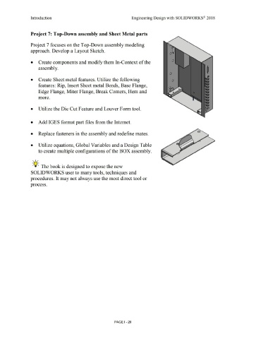
Project 7: Top-Down assembly and Sheet Metal parts
Project 7 focuses on the Top-Down assembly modeling
approach. Develop a Layout Sketch.
• Create components and modify them In-Context of the
assembly.
()
• Create Sheet metal features. Utilize the following ()
features: Rip, Insert Sheet metal Bends, Base Flange,
Edge Flange, Miter Flange, Break Comers, Hem and
more.
• Utilize the Die Cut Feature and Louver Form tool.
• Add IGES format part files from the Internet.
• Replace fasteners in the assembly and redefine mates.
• Utilize equations, Global Variables and a Design Table
to create multiple configurations of the BOX assembly.
, ,/
-;Q;. The book is designed to expose the new
SOLIDWORKS user to many tools, techniques and
procedures. It may not always use the most direct tool or
process.
PAGE I - 20