
Page 292 - Subyek Computer Aided Design - [David Planchard] Engineering Design with SOLIDWORKS
P. 292
Fundamentals of Drawing Engineering Design with SOLIDWORKS® 2018
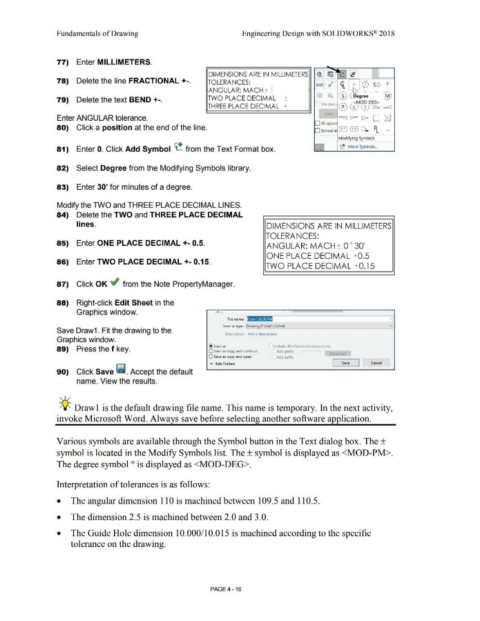
77) Enter MILLIMETERS.
DIMENSIONS ARE IN MILLIMETERS ~ [iJl !-=·· ··...u,.. _;_'c J....,------,-__1:=lj
78) Delete the line FRACTIONAL +-. TOLERANCES: ~ ~ <i_ (/) S(/) +
ANGULAR: MACH + I o
l\j ~ (D ~ egr; e - [@
79) Delete the text BEND+-. TWO PLACE DECIMAL + Use docu in\ (' ~~C?~..::.?EG> J
THREE PLACE DECIMAL + ~ "-9 \V- I=>, :....--:,
ff'n
Enter ANGULAR tolerance. "<:.) c::::--- t> D IZl
D Aii upper
80) Click a position at the end of the line. 0 Behind s @@ Q PL ...
Modifying Symbols
81) Enter 0. Click Add Symbol <t.! from the Text Format box. <t_! More Symbols ...
82) Select Degree from the Modifying Symbols library.
83) Enter 30' for minutes of a degree.
Modify the TWO and THREE PLACE DECIMAL LINES.
84) Delete the TWO and THREE PLACE DECIMAL
lines. DIMENSIONS ARE IN MILLIMETERS
TOLERANCES:
85) Enter ONE PLACE DECIMAL +- 0.5. ANGULAR: MACH+ 0 ° 30'
ONE PLACE DECIMAL +0.5
86) Enter TWO PLACE DECIMAL +- 0.15.
TWO PLACE DECIMAL +0.15
87) Click OK ~ from the Note PropertyManager.
88) Right-click Edit Sheet in the
Graphics window. ~ . . . .
File name: n v I
~~-----------~~
Save as type: Drawing (*.drw;*.slddrw) v
Save Draw1 . Fit the drawing to the
Description: Add a description
Graphics window.
@ save as Include all referenced components
89) Press the f key. O Save as copy and continue
Add prefix
Adv need
O Save as copy and open Add suffix ~
~ Hide Folders Save Cancel
90) Click Save ~ . Accept the default
name. View the results.
' I /
~Q~ Drawl is the default drawing file name. This name is temporary. In the next activity,
invoke Microsoft Word. Always save before selecting another software application.
Various symbols are available through the Symbol button in the Text dialog box. The ±
symbol is located in the Modify Symbols list. The ± symbol is displayed as <MOD-PM>.
The degree symbol is displayed as <MOD-DEG>.
O
Interpretation of tolerances is as follows:
• The angular dimension 110 is machined between 109.5 and 110.5.
• The dimension 2.5 is machined between 2.0 and 3.0.
• The Guide Hole dimension 10.000/10.015 is machined according to the specific
tolerance on the drawing.
PAGE4 - 16