
Page 561 - Subyek Computer Aided Design - [David Planchard] Engineering Design with SOLIDWORKS
P. 561
Engineering Design with SOLIDWORKS® 2018 Swept, Lofted and Additional Features
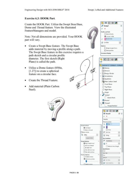
Exercise 6.3: HOOK Part.
~ ~ l~ l$ .~ I
Create the HOOK Part. Utilize the Swept Boss/Base,
,I> Sweep 1 (J)
Dome and Thread feature. View the illustrated
FeatureManagers and model.
Profile and Path
O Sketch Profile
Note: Not all dimensions are provided. Your HOOK @ Circular Profile
part will vary. C I ISketch-Path I
FBI
0 [o.,soin
• Create a Swept Base feature. The Swept Base Options
adds material by moving a profile along a path. O Merge tangent faces
12] Show preview
The Swept Base feature in this exercise requires a
Curvature Display v
path sketch and a circular profile
diameter. The first sketch (Right ~l~ lri2 l$ l~I >
Plane) is called the path. ~
+ ~ Exercise 6.3 (Default< <Default>
• Utilize a Dome feature (050in, • ~] History
[ 1.27]) to create a spherical ~ Sensors
feature on a circular face. • rtlJ Design Binder
• iAJ Annotations
[f:J Equations
• Create the Thread Feature. o-
:=i; Plain Carbon Steel
dJ Front Plane
• Add material (Plain Carbon dJ Top Plane
Steel). dJ Right Plane
L. Origin
.... , sweep1
[_ Sketch-Path
B Dome1
'4 LIJ Thread1
[_ Thread Profile1
~ ~ ~ $ ~
Cl) Thread1 (1j (1)
., x
...
Favorite v
Thread Location A
Co ~;Edge<l > I
Thread method:
tiE) I
@ cut thread I
O Extrude thread 0ottset
- -
D Mirror Profile ~ [o.01oin •
•
ti iodeg ffi t1 ~deg ~
Locate Profile End Condition A
Thread Options [II !Revolutions v •
c: ~ ~
@ Right-hand thread
O Left·hand thread
D Maintain thread length
D Multiple Start
Specification A
D Trim with start face
Type:
0 T rim with end face -
[inch Die vj
Preview Options
Size
O Shaded preview vj
[#10-24
@wireframe preview • '
•
I 0 j [0.1 soin ~
' I ~ I I [o.04166667in ~ ]
() Partial nreview •
PAGE 6 - 89