
Page 628 - Subyek Computer Aided Design - [David Planchard] Engineering Design with SOLIDWORKS
P. 628
Top-Down and Sheet Metal Parts Engineering Design with SOLIDWORKS® 2018
The Sketch Driven Pattern is complete. Suppress the patterns
when not required for future model development.
Utilize the Suppress option with configurations to save the
formed and flat state of the CABINET.
CABINET-Formed and Flat States
How do you control the 30 formed state in the assembly and
the 2D flat state in the drawing? Answer: Utilize
configurations. A configuration is a variation of a part or
assembly within a single document. Variations include
different dimensions, features, and properties.
The BOX assembly requires the CABINET in the 30 formed
state. Utilize the Default Configuration in the assembly.
The CABINET drawing requires the 2D flat state. The drawing requires a view with the
Linear Pattern of square cuts and the random sketch pattern suppressed. Create a new
configuration named NO-VENT. Suppress the patterns. Create a Derived configuration
named NO-VENT-FLAT. Un-suppress the Flat Pattern feature to maintain the CABINET
in its flat state. Create two configurations in the 3D formed and 2D flat state.
I Activity: CABINET-Fonned and Flat States
Display the ConfigurationManager and add a Configuration.
+ a
431) Drag the Split bar · + downward to divide the
FeatureManager in half.
Configurations
..... ~ CABI ,u;_-r..c;;.,,..,,:;,. .. ~,.ti , , I
432) Click the ConfigurationManager ~ tab.
~ . Part (CABINET)
ic Adi "Configuration ...
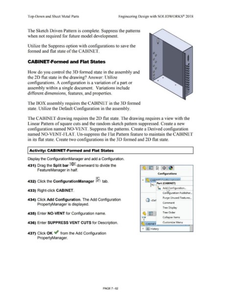
433) Right-click CABINET.
Configuration Publisher .. .
Purge Unused Features .. .
434) Click Add Configuration. The Add Configuration Q <oe ·
Comment
PropertyManager is displayed.
Tree Display
435) Enter NO-VENT for Configuration name. ~ ~ Tree Order
V Collapse Items
436) Enter SUPPRESS VENT CUTS for Description. ~ CABINtn ___ c_u_sto_m_iz_e _M_en_u _ r--r. , --1
I ~ ~ I History
I
437) Click OK ~ from the Add Configuration
PropertyManager.
PAGE? - 62