
Page 623 - Subyek Computer Aided Design - [David Planchard] Engineering Design with SOLIDWORKS
P. 623
Engineering Design with SOLIDWORKS® 2018 Top-Down and Sheet Metal Parts
Activity: Manufacturing Considerations-Sketch Linear Pattern
Suppress the louver.
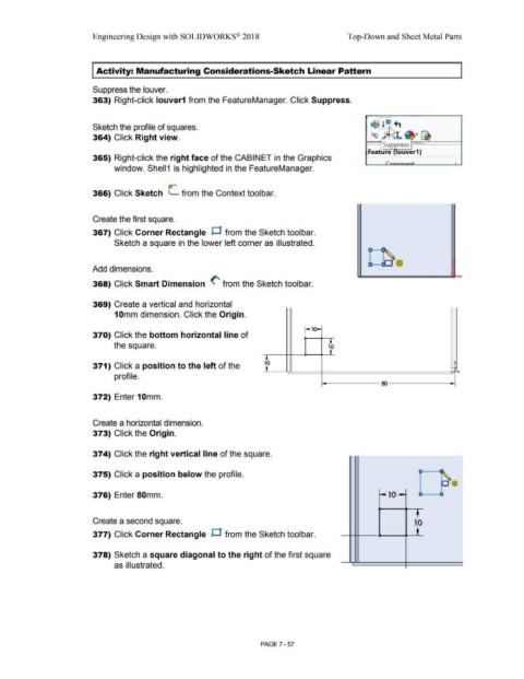
363) Right-click louver1 from the FeatureManager. Click Suppress.
Sketch the profile of squares.
364) Click Right view.
I~~ Suppress !-------'....___ __ _
Feature ouver1}
365) Right-click the right face of the CABINET in the Graphics
•
window. Shell1 is highlighted in the FeatureManager.
366) Click Sketch (_ from the Context toolbar.
Create the first square.
367) Click Corner Rectangle D from the Sketch toolbar.
Sketch a square in the lower left corner as illustrated.
Add dimensions.
368) Click Smart Dimension (' from the Sketch toolbar.
369) Create a vertical and horizontal
10mm dimension. Click the Origin.
r,01
370) Click the bottom horizontal line of -.
the square. 10
'
I
371) Click a position to the left of the 10 -
•
profile.
ro
372) Enter 10mm.
Create a horizontal dimension.
373) Click the Origin.
374) Click the right vertical line of the square. ~--
•
375) Click a position below the profile. -
376) Enter 80mm. -10~ u a
Create a second square. ' 10
___ .,___ .... __L
377) Click Corner Rectangle D from the Sketch toolbar.
378) Sketch a square diagonal to the right of the first square
as illustrated. •
PAGE? - 57