
Page 625 - Subyek Computer Aided Design - [David Planchard] Engineering Design with SOLIDWORKS
P. 625
Engineering Design with SOLIDWORKS® 2018 Top-Down and Sheet Metal Parts
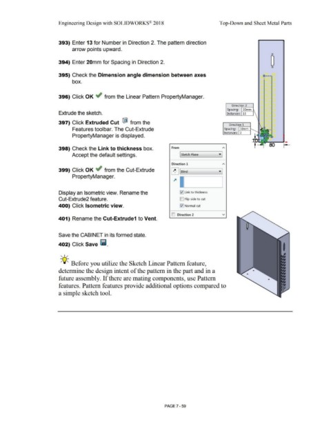
393) Enter 13 for Number in Direction 2. The pattern direction
arrow points upward.
0
394) Enter 20mm for Spacing in Direction 2.
0
395) Check the Dimension angle dimension between axes o----
box.
396) Click OK ~ from the Linear Pattern PropertyManager.
Direction 2
.------i
Spacing: 20mm
Extrude the sketch. Instances: 13
397) Click Extruded Cut ® from the
Direction 1
.------i
Features toolbar. The Cut-Extrude Spacing: 30mm
Instances: 2
PropertyManager is displayed.
80
398) Check the Link to thickness box. From
Accept the default settings. [ Sketch Plane
Direction 1
399) Click OK ~ from the Cut-Extrude
~ ['--sl_ind _____ __,• ]
PropertyManager.
Display an Isometric view. Rename the l'.l] Link to thickness
Cut-Extrude2 feature. D Flip side to cut
400) Click Isometric view. [:{] Normal cut
ID Direction 2 v
401) Rename the Cut-Extrude1 to Vent.
Save the CABINET in its formed state.
402) Click Save lill.
, 1 /
-;Q~ Before you utilize the Sketch Linear Pattern feature,
determine the design intent of the pattern in the part and in a
future assembly. If there are mating components, use Pattern
features. Pattern features provide additional options compared to
a simple sketch tool.
PAGE 7-59