
Page 620 - Subyek Computer Aided Design - [David Planchard] Engineering Design with SOLIDWORKS
P. 620
Top-Down and Sheet Metal Parts Engineering Design with SOLIDWORKS® 2018
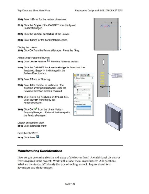
350) Enter 100mm for the vertical dimension.
8:
351) Click the Origin of the CABINET from the fly-out f , _ G-
FeatureManager. ~
352) Click the vertical centerline of the Louver.
-
8
353) Enter 55mm for the horizontal dimension.
Display the Louver.
354) Click OK from the FeatureManager. Press the f key.
Add a Linear Pattern of louvers.
[)C, 0
0
355) Click Linear Pattern eiei from the Features toolbar.
0
356) Click the CABINET back vertical edge for Direction 1 as
illustrated. Edge<1 > is displayed in the
Pattern Direction box.
Direction 1
,;;.--------1
Spacing: 25.00rnrn
Instances: 6
gg Linear Pattern
357) Enter 25mm for Spacing.
.; x
Direction 1 "" "
358) Enter 6 for Number of Instances. The
Z]~Edge<l>
direction arrow points upward. Click the
@ Spacing and instances
Reverse Direction button if required. •
O Up to reference
G 25.00mm
359) Click inside the Features and Faces box. 0
o"~ 6 - •
•
Click louver1 from the fly-out
Direction 2 v
FeatureManager.
!v'! Features and Faces
360) Click OK ~ from the Linear Pattern •
PropertyManager. LPattern2 is displayed in
the FeatureManager. I
Display an Isometric view.
361) Click Isometric view.
Save the CABINET.
362) Click Save Ii.
Manufacturing Considerations
How do you determine the size and shape of the louver form? Are additional die cuts or
forms required in the project? Work with a sheet metal manufacturer. Ask questions.
What are the standards? Identify the type of tooling in stock. Inquire about form
advantages and disadvantages.
PAGE? - 54