
Page 619 - Subyek Computer Aided Design - [David Planchard] Engineering Design with SOLIDWORKS
P. 619
Engineering Design with SOLIDWORKS® 2018 Top-Down and Sheet Metal Parts
CABINET-Louver Forming Tool
Form features such as louvers are added in the formed state. Formed features are
normally more expensive than cut features. Louvers are utilized to direct air flow. The
louvers are used to dissipate the heat created by the internal electronic components.
The forming tools folder contains numerous sheet metal forming shapes. In
SOLIDWORKS, the forming tools are inserted after the Bends are processed. Suppress
forming tools in the Flat Pattern.
Activity: CABINET-Louver Forming Tool
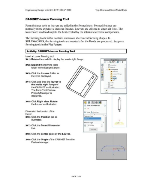
Insert a Louver Forming tool.
341) Rotate the model to display the inside right flange. « Desi n Libra .......
® · IJi. ~b C t '
342) Expand the forming tools fa) > ~ assemblies
folder in the Design Library. @ > 0 features
o v !!I forming tools
)~~ embosses
343) Click the louvers folder. A !!I extruded flanges
~
louver is displayed. !!I lances
~
!!I l~ers
i:ci
!"'! n
344) Click and drag the louver to
!c,> motion
the inside right flange of > O parts
the CABINET as illustrated. > lc'.; routing
The Form Tool Feature ~
louver
PropertyManager is
displayed.
-
•
•
345) Click Right view. Rotate •
•
•
I
•
•
the Louver as illustrated. ' •
•
•
$ Form Tool Feature (1) I
I
•
•
~ x •
•
•
-
Dimension the location of the
$ Type $ Position
louver.
Placement Face
346) Click the Position tab as
Face<1 > I
i II ustrated.
Rotation Angle
347) Click the Smart Dimension ~ 1270.00deg
tool.
I Flip Tool
348) Click the center point of the Louver.
349) Click the Origin of the CABINET from the
FeatureManager.
PAGE 7 - 53