
Page 614 - Subyek Computer Aided Design - [David Planchard] Engineering Design with SOLIDWORKS
P. 614
Top-Down and Sheet Metal Parts Engineering Design with SOLIDWORKS® 2018
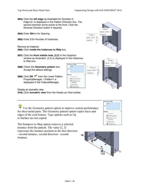
303) Click the left edge as illustrated for Direction 2.
Edge<2> is displayed in the Pattern Direction box. The
second direction arrow points to the front. Click the
Reverse Direction button if required.
Direction 1
Spacing: 125mm :
304) Enter 50mm for Spacing.
Direction 2 Instances: 3
1
:
Spacing: SOmm -
305) Enter 2 for Number of Instances. i:J
Instances: 2
A
Remove an Instance.
306) Click inside the Instances to Skip box. -
307) Click the front middle hole, (2,2) in the Graphics
window as illustrated. (2,2) is displayed in the Instances
to Skip box. Direction 1
Spacing: 125mrn : : I
Instances to Skip
308) Check the Geometry pattern box. (2, 2) Direction 2
Accept the default settings. Spacing: SOmm
• Instances: 2 ~
Options
A
309) Click OK if from the Linear Pattern Vary sketch
PropertyManager. LPattern1 is E2J Geometry pattern
E2J Propagate visual
displayed in the FeatureManager. properties
O Full preview
@ Partial preview
Display an Isometric view.
31 O) Click Isometric view from the Heads-up View toolbar.
Instances to Skip
, ,/ (2, 2)
;Q~ Use the Geometry pattern option to improve system performance
•
for sheet metal parts. The Geometry pattern option copies faces and Options
Vary sketch
edges of the seed feature. Type options such as Up
E2J Geometry pattern
to Surface are not copied. E2J Propagate visual
properties
O Full preview
The Instances to Skip option removes a selected @ Partial preview
instance from the pattern. The value (2, 2)
represents the instance position in the first direction
- second instance, second direction - second
instance.
•
/ ...
,,
PAGE 7 - 48