
Page 610 - Subyek Computer Aided Design - [David Planchard] Engineering Design with SOLIDWORKS
P. 610
Top-Down and Sheet Metal Parts Engineering Design with SOLIDWORKS® 2018
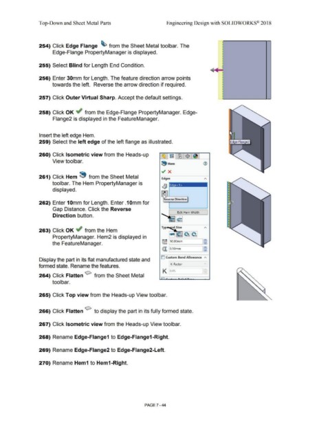
254) Click Edge Flange ~ from the Sheet Metal toolbar. The
Edge-Flange PropertyManager is displayed.
255) Select Blind for Length End Condition.
256) Enter 30mm for Length. The feature direction arrow points
towards the left. Reverse the arrow direction if required.
257) Click Outer Virtual Sharp. Accept the default settings.
258) Click OK ~ from the Edge-Flange PropertyManager. Edge-
Flange2 is displayed in the FeatureManager.
Insert the left edge Hem.
259) Select the left edge of the left flange as illustrated.
260) Click Isometric view from the Heads-up ~ ~~ $~
View toolbar.
~ Hem ®
~ x
261) Click Hem ~ from the Sheet Metal ~ges A
toolbar. The Hem PropertyManager is - -
Ed e<1>
displayed.
~
~
N"everse Direction
262) Enter 10mm for Length. Enter .10mm for
Gap Distance. Click the Reverse
Edit Hem Width
Direction button.
263) Click OK ~ from the Hem ca~ ~~
PropertyManager. Hem2 is displayed in
~ j10.oomm Jg
the FeatureManager.
@'. jo.1omm J~
D Custom Bend Allowance A
Display the part in its flat manufactured state and
K-Factor v
formed state. Rename the features.
K o.4s l~
264) Click Flatten ~ from the Sheet Metal
tool bar.
265) Click Top view from the Heads-up View toolbar.
266) Click Flatten ~ to display the part in its fully formed state.
267) Click Isometric view from the Heads-up View toolbar.
268) Rename Edge-Flange1 to Edge-Flange1-Right.
269) Rename Edge-Flange2 to Edge-Flange2-Left.
270) Rename Hem1 to Hem1-Right.
PAGE 7 - 44