
Page 608 - Subyek Computer Aided Design - [David Planchard] Engineering Design with SOLIDWORKS
P. 608
Top-Down and Sheet Metal Parts Engineering Design with SOLIDWORKS® 2018
Alternate between 30 formed and 2D flat for every additional sheet
metal feature you create. The Flatten feature alternates a sheet metal
part between the flat state and formed state.
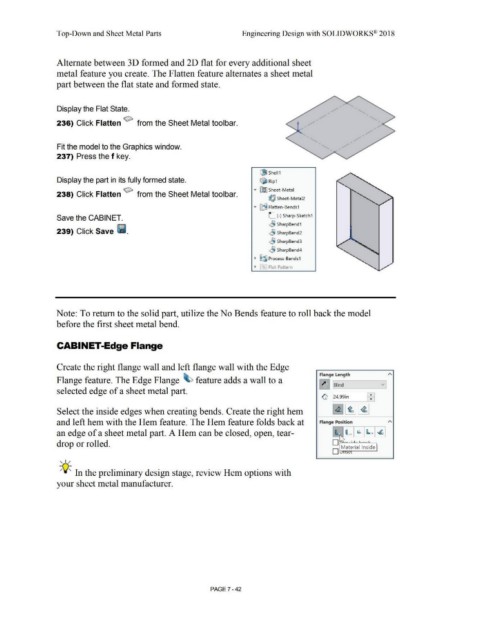
Display the Flat State.
236) Click Flatten ~ from the Sheet Metal toolbar.
Fit the model to the Graphics window.
237) Press the f key.
i!J Shell1
Display the part in its fully formed state. ~ Rip1
• ~ Sheet-Metal
238) Click Flatten ~ from the Sheet Metal toolbar.
~ Sheet-Metal2
.-
..,. [1i Flatten-Bends1
Save the CABINET. L (-) Sharp-Sketch1
~ SharpBend 1
239) Click Save 111. ~ SharpBend2
,.9 Sharp8end3
..§j SharpBend4
• ~~ Process-Bends1
• ~· Flat-Pattern
Note: To return to the solid part, utilize the No Bends feature to roll back the model
before the first sheet metal bend.
CABINET-Edge Flange
Create the right flange wall and left flange wall with the Edge
Flange Length "'
Flange feature. The Edge Flange ~ feature adds a wall to a
~ Blind v
selected edge of a sheet metal part.
~ ~: I
124.99in
Select the inside edges when creating bends. Create the right hem ~ ~ ~
and left hem with the Hem feature. The Hem feature folds back at Flange Position "'
an edge of a sheet metal part. A Hem can be closed, open, tear- !lr- b ~ ~ ~
o rit -··-· .
drop or rolled.
D Material Inside
J I '
, ,/
-;Q~ In the preliminary design stage, review Hem options with
your sheet metal manufacturer.
PAGE 7 - 42