
Page 605 - Subyek Computer Aided Design - [David Planchard] Engineering Design with SOLIDWORKS
P. 605
Engineering Design with SOLIDWORKS® 2018 Top-Down and Sheet Metal Parts
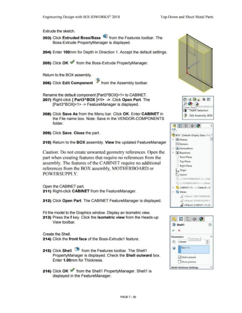
Extrude the sketch.
203) Click Extruded Boss/Base ~ from the Features toolbar. The
Boss-Extrude PropertyManager is displayed.
204) Enter 1 OOmm for Depth in Direction 1. Accept the default settings.
205) Click OK ~ from the Boss-Extrude PropertyManager.
Return to the BOX assembly.
206) Click Edit Component ~ from the Assembly toolbar.
Rename the default component [Part3"BOX]<1 > to CABINET.
207) Right-click [ Part3ABOX ]<1> ->. Click Open Part. The
[Part3"BOX]<1 > -> FeatureManager is displayed.
Open P~a~rt ~ ===i==I
n~e Selection
208) Click Save As from the Menu bar. Click OK. Enter CABINET in
~ Edit Assembly: BOX
the File name box. Note: Save in the VENDOR-COMPONENTS
folder.
~1~ 1~:$ 1e,1 >
)]~
209) Click Save. Close the part.
~ BOX (Default< Display State-1 >) ""
• [€}] History
210) Return to the BOX assembly. View the updated FeatureManager
lfiJ Sensors
• IA] Annotations
Caution: Do not create unwanted geometry references. Open the • ~ Equations
part when creating features that require no references from the [P Front Plane
[P Top Plane
assembly. The features of the CABINET require no additional
[P Right Plane
references from the BOX assembly, MOTHERBOARD or
l... Origin
POWERSUPPL Y. L. Layout
'
r (-) MOTHERBOARD<2> (Def
r
"-' (-) POWERSUPPLY<1 > (Defa1
Open the CABIN ET part. • ~ CABINET <1 > -> (Default <<[
211) Right-click CABIN ET from the FeatureManager. • ®@ Mates
~ lnPlace1 (MOTHERBOAR
212) Click Open Part. The CABINET FeatureManager is displayed. b lnPlace2 (POWERSUPPLY
" lnPlace3 (CABINET <1 >,F1
Fit the model to the Graphics window. Display an Isometric view.
213) Press the f key. Click the Isometric view from the Heads-up ~ ~ ~ $
View toolbar.
GS Shell1
Create the Shell.
Parameters I ) ~
214) Click the front face of the Boss-Extrude1 feature. ~ Thickness ---gJ
~ l_,.vmml ~
1
215) Click Shell l1- from the Features toolbar. The Shell 1
•
PropertyManager is displayed. Check the Shell outward box.
E2] Shell outward
Enter 1.00mm for Thickness.
D Show preview
Multi-thickness Settings v
216) Click OK ~ from the Shell1 PropertyManager. Shell1 is
displayed in the FeatureManager.
PAGE 7 -39